

Description
- Brand: GE Fanuc
- Full Model Number: IC670MDL644
- System/Series Family: GE Field Control Distributed I/O
- Core Function: 16-point grouped positive/negative-logic fast discrete input acquisition
- Top 3 Hardcore Specs: 16 inputs; 12/24 VDC field input; 25 µs typical ON response
- Rated Voltage: 24 VDC
- Input Voltage Range: 0–30 VDC
- Logic Polarity: Positive or negative logic
- User Input Current: 8.0 mA maximum per point at 24 VDC
- Input Impedance: 3 kΩ typical
- ON-State Current: 3–8 mA
- OFF-State Current: 0–1.5 mA
- Response Time: 25 µs typical ON response; 60 µs maximum
- Input Data: 16 bits / 2 bytes
- Field Power: External 24 VDC required for input devices
- Backplane Logic Power: Supplied through the Bus Interface Unit
- Indicators: Individual input LEDs plus PWR LED
- Stock Status: New Surplus or Fully Tested Refurbished; exact revision to be confirmed
GE Fanuc documentation identifies IC670MDL644 as a 12/24 VDC positive/negative-logic fast input module with 16 grouped discrete inputs.
Module 3: Technical Product Introduction
Fast discrete sensing is useful when a control event must be captured without introducing milliseconds of unnecessary input delay. The GE Fanuc IC670MDL644 is a 16-point Field Control discrete-input module designed for 12/24 VDC positive or negative logic. The module accepts signals from either polarity arrangement and passes the resulting 16 bits of input data to the GE Field Control Bus Interface Unit. Each input has a dedicated logic-side LED, while the PWR indicator confirms the required field and backplane power conditions.
Its speed is the main reason to select this model over a conventional discrete-input card. The documented input voltage range is 0–30 VDC, with approximately 3 kΩ input impedance and an input current of up to 8 mA per point at 24 VDC. Typical ON response is 25 µs, with a maximum of 60 µs. The positive-logic ON region is approximately +15 to +30 VDC, while negative-logic operation uses approximately -15 to -30 VDC. The module provides two bytes of input data, processed by the associated Bus Interface Unit rather than by an onboard processor. (pdfsupply.com)
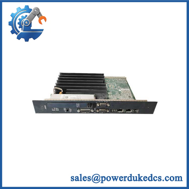
GE IC670MDL644
Module 4: Application Scenarios & Field Realities
- For high-speed machine status signals, IC670MDL644 can capture fast-changing 12/24 VDC discrete inputs with a typical 25 µs ON response. This is useful for limit switches, proximity sensors, machine interlocks, and other events where slower input filtering can obscure the actual sequence.
- Where field devices use opposite sourcing conventions, the positive/negative logic capability allows the same input module to accommodate either sourcing or sinking-style circuit arrangements. The wiring must still follow the correct commoning and terminal configuration; polarity flexibility does not mean every wiring arrangement is interchangeable.
- Inside a GE Field Control distributed I/O station, the module depends on the Bus Interface Unit for host-side processing and system communication. A healthy input LED therefore proves the local field signal path, not necessarily the complete data path back to the controller.
- During troubleshooting of intermittent fast inputs, inspect both the external 24 VDC field supply and the terminal block. Voltage drop, poor contact resistance, or electrical noise can affect an input even though the module itself remains within specification (particularly on long machine wiring).
Module 5: Migration, Compatibility & Installation Traps
Replacement Matrix
Replacement classification: Drop-in Replacement when the existing station is configured for IC670MDL644 with the compatible GE Field Control terminal block, Bus Interface Unit, field voltage, and module keying arrangement.
Software compatibility: Configuration verification required. The module has no application firmware of its own. Input defaults, fault reporting, and host-side interpretation are handled by the Bus Interface Unit or higher-level controller, so station configuration must match the replacement module.
Cross-model replacement: Hardware and configuration verification required. IC670MDL640 is also a 24 VDC positive/negative-logic input module, but IC670MDL644 is specifically the fast-input version. Other Field Control input modules can have different voltage ranges, response times, or isolation characteristics.
Field Traps — Watch Out
1. Do not confuse with IC670MDL640. Both are 16-point positive/negative-logic input modules, but the 644 is specifically designed for fast input acquisition. Replacing it with a standard 640 can materially change input response characteristics.
2. Verify the field supply at the module terminals. Although the nominal rating is 24 VDC, the documented input range is 0–30 VDC. Measure the actual voltage under operating conditions rather than relying on the power-supply nameplate.
3. Preserve the polarity arrangement. Positive and negative logic use different field-current paths. Before changing terminal wiring, document which common and input arrangement is used on the existing terminal block.
4. Do not remove or insert the module casually during station operation. GE documentation warns that inserting or removing an I/O module while the station is operating may cause incorrect data to be generated. Follow the approved maintenance procedure and isolate the station when required.
5. Keying must match the module type. Field Control modules use optional mechanical keying locations to prevent an incompatible module from being installed into the wrong terminal block. Preserve the original key positions when replacing the module.
Module 6: Quality Assurance SOP
Pre-Shipment Inspection Protocol for GE
- OEM identity inspection: Verify GE Fanuc marking, exact designation, hardware revision, serial number, and module identification label.
- Variant verification: Confirm the module is rather than IC670MDL640 or another Field Control discrete-input model.
- Mechanical inspection: Examine the housing, module keying features, terminal interface, locking surfaces, LED window, and accessible PCB areas for cracks, deformation, corrosion, contamination, or unauthorized modification.
- Connector inspection: Check the terminal-block interface for oxidation, bent contacts, contamination, poor mechanical retention, or evidence of overheating.
- Keying verification: Compare the installed module’s mechanical key positions with the intended terminal-block arrangement before bench installation.
- Power-on verification: Install the module on a compatible Field Control terminal block and Bus Interface Unit, apply the documented 24 VDC field supply, and monitor startup current and abnormal temperature rise.
- PWR indication test: Confirm correct operation of the PWR LED with both field and backplane power present.
- 16-channel verification: Exercise all 16 inputs independently and record each channel’s response.
- Positive-logic test: Apply calibrated positive-voltage inputs and verify correct recognition through the specified +15 to +30 VDC region.
- Negative-logic test: Apply calibrated negative-voltage inputs and verify correct recognition through the specified negative-logic operating region.
- Threshold verification: Apply controlled voltage levels through the transition region and record ON/OFF behavior for representative channels.
- Response-time verification: Use an appropriate pulse generator and oscilloscope or time-correlated test fixture to verify the expected 25 µs typical / 60 µs maximum ON response.
- Current verification: Measure representative input current at 24 VDC and compare against the documented 8 mA maximum per point requirement.
- Input-impedance verification: Check representative input impedance against the approximately 3 kΩ typical specification.
- LED verification: Confirm that each of the 16 individual logic-side LEDs follows the corresponding input state without intermittent flicker or false indication.
- Host-data verification: Connect to a compatible Bus Interface Unit and verify that all 16 input bits are transmitted correctly to the host system.
- Fast-transition test: Exercise repeated short-duration pulses within the approved test limits and confirm that the input circuitry responds consistently without unexpected missed states.
- Fault simulation: Where the test environment permits, simulate signal loss and abnormal field conditions and confirm the expected host-side diagnostic response.
- Thermal observation: Operate multiple channels simultaneously under representative field loading and monitor for abnormal temperature rise or input-state instability.
- Final QC record: Record exact model, revision, serial number, terminal block, BIU used, supply voltage, all 16 channel results, positive/negative logic results, response-time measurements, current measurements, host-data results, test date, and inspector approval.
- ESD-controlled packaging: Place the module in an ESD-safe package and protect the connector interface, keying features, LED window, and housing against impact, moisture, contamination, and electrostatic discharge.
Procurement note: The technically supported identity is GE Fanuc — 16-point 12/24 VDC Positive/Negative Logic Fast Input Module for the Field Control distributed I/O system. Its defining characteristics are 0–30 VDC input capability, 8 mA maximum input current per point, approximately 3 kΩ input impedance, 25 µs typical ON response, 60 µs maximum response, and 16 bits of input data. The module requires a compatible Field Control terminal block and Bus Interface Unit.











 Start Chat


