

Description
- Brand: GE Fanuc
- Full Model Number: IC670MDL740
- System/Series Family: GE Field Control distributed I/O system
- Core Function: 16-point positive-logic discrete output module for sourcing 10–30 VDC field loads
- Top 3 Hardcore Specs: 16 outputs; 10–30 VDC input supply, 24 VDC nominal; 0.5 A maximum per point / 4 A per module
- Stock Status: Verify current New Surplus, Factory Sealed, or Fully Tested Refurbished condition before order
Module 3: Technical Product Introduction
When a decentralized I/O station has to switch multiple 24 VDC field devices, output topology matters just as much as channel count. GE IC670MDL740 is a 16-point positive-logic discrete output module in the GE Field Control family. The outputs are sourcing type: they switch the load to the positive side of the DC supply and therefore supply current to the connected load. The module’s electronics receive their operating power from the Bus Interface Unit, while a separate external DC source powers the field loads.
The electrical limits are clearly defined. User field supply is 10–30 VDC, 24 VDC nominal, with 4 A maximum per module. Each output is rated at 0.5 A maximum, with an output voltage range of approximately 9.2–29.5 VDC. GE specifies a maximum output voltage drop of 0.5 V, maximum leakage of 0.5 mA at 30 VDC, and approximately 200 µs maximum ON and OFF response time with a 0.5 A resistive load. A common 5 A, 250 V slow-blow fuse protects the external field supply path.
Module 4: Application Scenarios & Field Realities
- Inside a GE Field Control remote I/O station, IC670MDL740 provides 16 sourcing outputs for discrete field devices. Typical loads include interposing relay coils, solenoid valves, indicators, and machine-control actuators. The module is intended for decentralized I/O rather than a standalone CPU.
- When several 24 VDC loads operate simultaneously, the 4 A module limit becomes the controlling value. Even when every individual load remains below the 0.5 A channel rating, the combined demand cannot exceed the module’s total current specification.
- For relay-coil activation and machine automation, the sourcing architecture is useful because the output supplies the positive side of the field circuit. Packaging lines, conveyor systems, and discrete machine-control panels are typical Field Control applications.
- During a brownfield replacement, the external field supply must be treated separately from BIU power. The module itself is powered through the Bus Interface Unit, while the load-switching circuitry uses an external DC source. A missing or undervoltage field supply can therefore appear as a module fault even when the BIU is healthy.
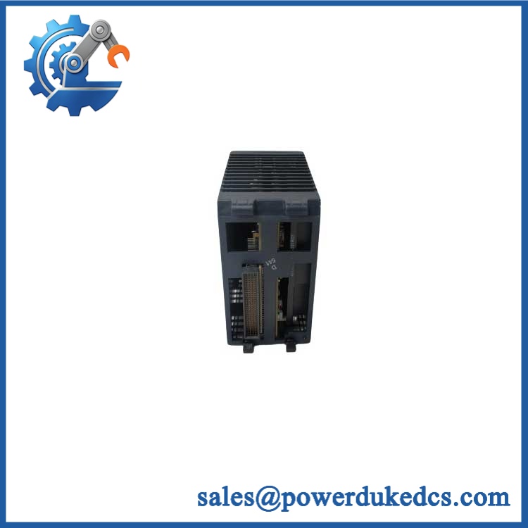
GE IC670MDL740
Module 5: Migration, Compatibility & Installation Traps
Replacement Matrix
Exact IC670MDL740 with matching Field Control configuration: Drop-in Replacement
When the installed station uses IC670MDL740 with the correct BIU generation, terminal base, field supply, and output assignment, the module can normally be exchanged directly.
IC670MDL740 revision change: Software Compatible / Hardware Verification Required
The Field Control family includes multiple revisions of the MDL740. Verify the complete catalog number and revision, BIU compatibility, terminal arrangement, and station configuration before releasing the spare.
IC670MDL742 substituted for : Hardware Modification Required
MDL742 is a different output design, described as a 5/12/24 VDC negative-output module. It is not a direct equivalent to the positive-logic sourcing outputs of MDL740.
IC670MDL730 substituted for : Hardware Modification Required
MDL730 is an 8-point 24 VDC output module with electronic short-circuit protection, while MDL740 provides 16 grouped positive outputs and a different protection architecture. Channel count and wiring must therefore be checked before substitution.
⚠️ Field Traps (Watch Out)
Sourcing-versus-sinking trap: uses positive-logic sourcing outputs. The load is switched toward the positive supply. Replacing it with a sinking-output module without reviewing the field wiring can reverse the intended circuit topology.
Module-current trap: The maximum is 0.5 A per point, but the module-wide limit is 4 A. Calculate the simultaneous load, especially when multiple solenoids or relay coils can energize during the same machine cycle.
Field-power trap: The module’s logic power comes from the BIU, but the output load supply comes from an external DC source. Verify the external source and its fuse before condemning the module. GE specifies monitoring of this user supply, with a field-voltage fault below approximately 9.8 VDC.
BIU-generation trap: GE Field Control documentation shows that some modules require specific BIU revisions. The MDL740 belongs to the distributed Field Control family, so check the installed BIU revision and station configuration rather than treating every Field Control base as universally interchangeable.
Module 6: Quality Assurance SOP
Pre-Shipment QA Protocol for GE
- Step 1 — Identity Verification: Confirm GE Fanuc marking, model number, revision, serial or manufacturing information, and associated Field Control station and BIU identification.
- Step 2 — OEM Anti-Counterfeit Visual Inspection: Inspect labels, barcode markings, PCB identifiers where accessible, terminal interfaces, module housing, LEDs, and evidence of unauthorized modification.
- Step 3 — Mechanical Inspection: Check the terminal interface, module housing, retention features, connector contacts, and enclosure for cracks, deformation, corrosion, contamination, or bent contacts.
- Step 4 — Field-Supply Verification: Confirm the external load supply is within the specified 10–30 VDC range and verify the protective fuse before energizing the outputs.
- Step 5 — Power-On Self-Test: Install the module in a compatible Field Control station and verify BIU recognition, module status, PWR indication, and absence of configuration faults.
- Step 6 — Sixteen-Channel Output Test: Exercise all 16 output points individually using controlled loads. Record commanded state, measured voltage, load current, and LED indication.
- Step 7 — Current-Capacity Test: Test representative channels at controlled currents while remaining below the 0.5 A per-point limit and verify that the aggregate test load remains below 4 A.
- Step 8 — Voltage-Drop Verification: Measure output voltage under representative load and compare the result against the specified output characteristics, including the maximum stated voltage drop.
- Step 9 — Field-Supply Fault Test: Where the laboratory fixture supports it, simulate a controlled low-field-voltage condition and verify the expected power/fault indication without exposing production wiring to an uncontrolled fault.
- Step 10 — Final QC Record: Record model, revision, BIU configuration, field-supply voltage, all 16 channel results, load currents, output voltage measurements, diagnostic behavior, visual condition, test date, and final QC disposition.
Technical Verification Note: GE Fanuc documentation identifies as a 12/24 VDC positive-output module with 16 grouped sourcing outputs. The published specifications are 10–30 VDC user supply, 24 VDC nominal, 0.5 A maximum per point, 4 A maximum per module, 9.2–29.5 VDC output range, 0.5 V maximum output drop, 0.5 mA maximum leakage at 30 VDC, and approximately 200 µs maximum ON/OFF response with a 0.5 A resistive load.
Configuration Control Note: The is a Field Control distributed I/O module, not a standalone PLC CPU. The BIU handles intelligent processing and host communication, while the module provides the physical output switching. The external field supply, terminal base, BIU revision, and module revision should all be included in the spare-parts record.











 Start Chat


