

Description
- Brand GE Fanuc / GE
- Full Model Number IC670MDL930K
- System/Series Family GE Fanuc Genius Field Control
- Core Function 8-point isolated relay output module with six Form A and two Form C contacts
- Top 3 Hardcore Specs 8 relay outputs | 5–265 VAC / 5–125 VDC contact capability | 2 A pilot-duty rating
- Stock Status New Surplus — verify Series K revision, terminal base, field voltage, and load configuration before shipment
Module 3: Technical Product Introduction
When a Field Control station needs to switch independent AC or DC field circuits, a solid-state output is not always the right interface. GE IC670MDL930K is an 8-point isolated relay output module in the Genius Field Control family. Its contact arrangement combines six normally open Form A outputs with two Form C outputs providing both normally open and normally closed contacts. The module’s internal relay coils are powered from the Bus Interface Unit, while an external AC or DC source supplies the actual field loads.
The K suffix identifies a specific Series K version of the IC670MDL930 family. Published technical data for the family specifies 5–265 VAC or 5–125 VDC contact operation, with a maximum resistive load of approximately 2 A per point under the applicable voltage conditions, while the family is also commonly listed at 16 A total module capacity depending on the load and voltage combination. The module draws up to approximately 313 mA from BIU power, uses fixed-coil moving-armature relays, and provides individual output-status LEDs.
Module 4: Application Scenarios & Field Realities
- Inside a legacy Genius Field Control station, IC670MDL930K can switch individually isolated field circuits such as motor-control relays, annunciators, contactors, and other discrete loads. The six Form A plus two Form C arrangement is useful when both NO-only and changeover contacts are needed in the same station. ([turn406579search23]
- For applications requiring normally closed feedback, the two Form C channels provide an NC contact as well as an NO contact. That distinction matters when a replacement is being checked against cabinet drawings; substituting an eight-point NO-only relay module would change the field circuit behavior.
- When several output faults appear simultaneously, check the shared BIU and field supply before replacing the relay card. Module logic power comes from the BIU, while the loads are supplied by an external AC/DC source. A loss of either supply path can create symptoms that resemble a failed output assembly. ([turn406579search2]
- During maintenance on an aging Field Control cabinet, relay contact condition deserves particular attention. Mechanical wear, contact oxidation, welded contacts, or excessive arcing can cause intermittent output behavior even when the channel LED responds correctly.
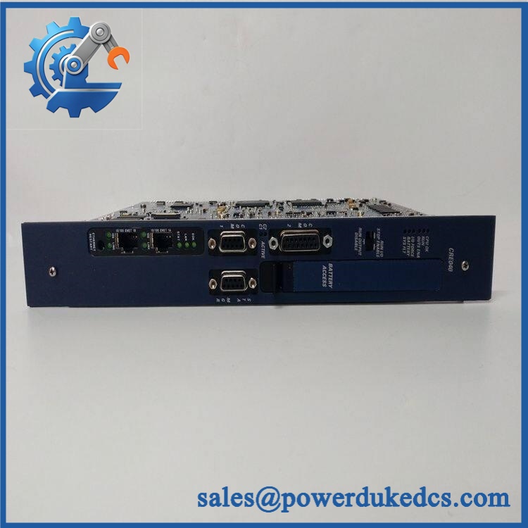
GE IC670MDL930K
Module 5: Migration, Compatibility & Installation Traps
Replacement Matrix
| Replacement Status | Engineering Assessment |
|---|---|
| Drop-in Replacement | Yes, for a like-for-like IC670MDL930K replacement using the compatible Field Control terminal base, BIU, keying arrangement, and field-load configuration. |
| Software Compatible | Generally yes for an exact relay-output replacement. The module has no user application firmware; output data and fault behavior are managed by the BIU or host system. |
| Hardware Modification Required | Normally no for an exact Series K replacement. Modification may be required when changing relay-output architecture, contact form, terminal hardware, or BIU generation. |
⚠️ Field Traps: Watch Out
Check the contact arrangement, not just the eight-point count. IC670MDL930 provides six Form A contacts and two Form C contacts. The Form C channels have both NO and NC terminals, while the Form A channels are NO only.
Do not apply the headline 2 A rating to every voltage condition. GE’s published family data differentiates the permissible load according to AC/DC voltage and load type. Current technical references list 2 A pilot duty, while the detailed specification gives different maximum currents at higher DC voltages. ([turn406579search3]turn406579search23)
Verify the external load supply. The relay coils are powered from the BIU, but the field contacts require an external AC and/or DC source. A powered BIU does not prove that the field-load supply is present.
Protect inductive loads correctly. Contactors, relay coils, and solenoids can produce substantial switching transients. GE’s relay-output documentation provides snubber provisions and load limitations; the field load should be evaluated using the actual voltage, current, power factor, and suppression arrangement.
Check the Series K revision. IC670MDL930K is specifically the Series K version. Do not assume unrestricted interchangeability among E, J, and K revisions without checking the project hardware baseline. Current supplier records list E, J, and K as distinct revisions of the MDL930 family.
Preserve the terminal-base keying. Field Control modules use optional keying positions to prevent installation into an incompatible terminal assembly. Photograph the original keying arrangement before replacement.
Module 6: Quality Assurance SOP
A surplus IC670MDL930K should be tested as an eight-channel mechanical relay assembly together with a compatible BIU and terminal base.
- OEM anti-counterfeit visual inspection: Verify GE Fanuc identification, exact marking, Series K designation, product label, PCB revision, relay arrangement, connector geometry, and visible manufacturing codes against controlled references.
- Part-number and traceability check: Record the complete number, Series K revision, serial/date code, terminal-base reference, and BIU model/revision.
- Mechanical inspection: Examine the housing, terminal interface, connector contacts, keying features, relay section, mounting surfaces, and PCB for cracks, corrosion, contamination, bent contacts, or unauthorized rework.
- BIU compatibility verification: Confirm that the test station uses a compatible Genius Bus Interface Unit and that the host configuration recognizes the MDL930 family.
- Power-on self-test (POST): Install the module in a known-good Field Control station and verify the PWR indication and all individual channel LEDs during controlled output commands.
- Relay-coil verification: Confirm the module receives its operating power from the BIU and measure representative coil current against the controlled reference.
- Eight-channel functional test: Command all eight outputs individually and verify that each relay operates reliably without chatter or intermittent pickup.
- Contact-form verification: Confirm six Form A channels provide the expected NO operation and two Form C channels provide correct NO and NC switching.
- Contact-resistance test: Measure closed-contact resistance on every channel where practical and investigate unstable or unusually high values.
- Open-contact insulation test: Verify open-contact insulation and channel isolation using the approved laboratory method.
- AC load test: Exercise representative contacts with controlled AC loads within the applicable voltage/current limits, including a suitable resistive load and, where authorized, an inductive load.
- DC load test: Exercise representative contacts with controlled DC loads and verify behavior across the applicable voltage range. Pay particular attention to higher-voltage DC applications, where contact current capability is lower than the nominal low-voltage rating.
- Inrush test: Where the laboratory fixture permits, apply a controlled transient representative of the connected load and verify that relay contacts do not weld, chatter, or exhibit abnormal arcing.
- Switching-cycle test: Cycle representative relays under controlled loading and monitor contact resistance, timing, and mechanical consistency.
- LED verification: Confirm each channel LED corresponds to the correct physical relay output and changes state with the commanded output.
- Isolation verification: Verify the documented relay contact and group isolation using the approved dielectric test procedure. The family documentation specifies isolation requirements for the applicable Field Control terminal arrangement.
- Automatic fault-reporting verification: Use the approved BIU/host test environment to confirm that expected module fault and output-status information is correctly reported.
- Terminal-base verification: Confirm proper mating, terminal allocation, keying, and field-power routing through the exact terminal base used by the application.
- Communication handshake verification: Verify successful host-to-BIU-to-module output-command exchange. does not independently implement a plant communication protocol; the BIU provides the Field Control network interface.
- Field-load simulation: Test representative relay, contactor, annunciator, or solenoid loads through the complete terminal-base path and verify stable switching.
- Extended-run test: Operate representative relay outputs through repeated switching cycles while monitoring contact resistance, coil current, temperature, LED status, and intermittent faults.
- Final QC record: Document Series K revision, BIU compatibility, eight-channel output results, Form A/Form C verification, contact resistance, insulation results, load conditions, switching-cycle performance, fault reporting, extended-run observations, traceability, and packaging condition.
Technical Identification Note: GE Fanuc’s technical documentation identifies IC670MDL930 as a Relay Isolated, NO/NC Output Module with eight isolated relay outputs: six Form A and two Form C. Current supplier records identify as the Series K revision. The family uses external AC/DC field power, while module logic power comes through the BIU. Published data specifies a broad contact-voltage capability but load current varies with voltage and load type; the detailed GE speification should therefore govern the final application rating.











 Start Chat


