

Description
- Brand: GE Fanuc
- Full Model Number: IC687BEM713
- System/Series Family: Series 90-70 / PACSystems RX7i Genius Bus Expansion
- One-Sentence Core Function: Bus Transmitter Module for connecting a Series 90-70 expansion rack to the controller-side bus architecture
- Top 3 Hardcore Specs: 500 Kbytes/sec effective data rate; 50 ft maximum interconnecting cable; supports up to 7 expansion racks
- Stock Status: New Surplus / Fully Tested Refurbished — verify rack architecture, cable length, and paired bus hardware before shipment
Module 3: Technical Product Introduction
A remote expansion-rack fault can look like an I/O failure when the actual interruption is in the rack-to-rack communication path. The GE IC687BEM713 is a Bus Transmitter Module for the Series 90-70 architecture, used to provide the transmission side of the expansion-bus connection. GE documentation identifies the IC687BEM713 as a 1/2-slot bus transmitter, while later PACSystems documentation lists it among the Series 90-70 bus-expansion modules supported by RX7i expansion-rack configurations.
The communication path operates at an effective 500 Kbytes/sec data rate, with a documented 50 ft (15 m) maximum interconnecting cable length and support for up to seven expansion racks. The module occupies half of a standard 90-70 slot width and uses dedicated interconnection hardware rather than functioning as a generic Ethernet interface. GE’s Series 90-70 reference data also identifies a programmer interface and dedicated bus-transmitter architecture.
Module 4: Application Scenarios & Field Realities
- In a Series 90-70 system using expansion racks, the IC687BEM713 provides the transmitter side of the expansion-bus path. When an entire remote rack disappears from the controller’s I/O image, check this module, the mating receiver hardware, interconnecting cable, and rack power before replacing individual I/O cards.
- When diagnosing an intermittent remote-rack communication fault, inspect the inter-rack cable first. GE’s published data limits the interconnecting cable to 50 ft / 15 m for this bus-transmitter arrangement. Exceeding that distance can turn a marginal installation into a recurring communication problem.
- For systems with several expansion racks, the seven-rack limit matters during architecture review. A cabinet drawing showing more than seven supported expansion racks requires confirmation that another supported architecture or controller arrangement is being used rather than simply adding another BEM713. ([turn0search24])
- During RX7i migration work, do not discard existing Series 90-70 expansion hardware without checking compatibility. GE’s PACSystems documentation explicitly lists IC687BEM713 among the Series 90-70 bus-expansion modules supported by RX7i expansion-rack arrangements.
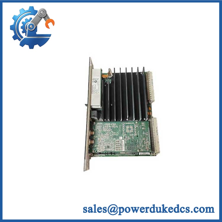
GE IC687BEM713
Module 5: Migration, Compatibility & Installation Traps
Replacement Matrix
| Replacement Type | Assessment |
|---|---|
| Drop-in Replacement | Yes, for an exact IC687BEM713 replacement in a compatible Series 90-70 expansion-bus architecture |
| Software Compatible | Normally yes at the module level; the controller configuration and rack mapping must still be verified after replacement |
| Hardware Modification Required | Normally no for like-for-like replacement; expansion-rack cabling, paired bus hardware, and rack arrangement must match |
⚠️ Field Traps — Watch Out
1. Do not confuse the BEM713 with the Genius Bus Controller.
GE documentation distinguishes the Bus Transmitter Module from the Genius Bus Controller (GBC). The BEM713 is not the CPU-side Genius controller and should not be cataloged as one. ([turn0search25])
2. The cable length is part of the bus specification.
The documented maximum interconnecting cable is 50 ft (15 m). Verify the installed cable length and construction before blaming the transmitter module for intermittent communication.
3. Expansion-rack count must remain within the supported architecture.
The published BEM713 data identifies support for up to seven expansion racks. Do not infer unlimited rack expansion from the module’s physical compatibility with a Series 90-70 backplane.
4. Preserve the half-slot mechanical arrangement.
The is specified as a 1/2-slot version. Confirm the original rack position and mechanical clearance before inserting a replacement or a visually similar full-width module. ([turn0search24])
Module 6: Quality Assurance SOP
- OEM anti-counterfeit visual inspection — inspect GE Fanuc identification, marking, PCB labels, connector hardware, front-panel indicators, and visible manufacturing details.
- Exact part-number verification — confirm character-for-character against the purchase order and physical module label.
- Architecture verification — confirm that the intended application uses a compatible Series 90-70 expansion-rack bus and that the is installed in the documented transmitter position.
- Mechanical inspection — inspect the half-slot housing, backplane connector, cable interface, mounting hardware, and PCB surfaces for bent contacts, corrosion, contamination, cracks, or impact damage.
- Power-on self-test (POST) — energize the module in an approved Series 90-70 test rack and record module status, LED indications, current behavior, and abnormal temperature rise.
- Bus-cable inspection — verify the interconnecting cable type, connector condition, routing, shielding, and measured length. Confirm that the installation remains within the documented 50 ft / 15 m limit.
- Expansion-bus communication test — connect the BEM713 to compatible receiver hardware and establish the expansion-rack communication path under controlled laboratory conditions.
- Data-rate verification — verify stable operation at the documented effective 500 Kbytes/sec rate using the approved diagnostic/test environment.
- Rack-recognition verification — connect a compatible expansion rack and confirm that the controller recognizes the rack and its configured I/O image without persistent bus faults.
- Multi-rack validation — where the test environment supports it, verify the expected controller response with representative expansion-rack configurations and confirm the installation remains within the documented maximum of seven expansion racks.
- Fault simulation — use an approved fixture to simulate cable interruption, receiver loss, or transmitter communication faults and confirm that the controller reports the expected rack/bus diagnostic condition.
- Controller configuration verification — verify the rack address/location and I/O configuration against the application database after the communication link is restored.
- Communication handshake verification — confirm stable data exchange between the controller, transmitter/receiver path, and expansion rack. This is the appropriate functional communication test; the BEM713 is not independently tested as an Ethernet or Modbus device.
- Final QC and packaging — document exact model number, hardware revision, cable length, communication results, rack-recognition test, diagnostic status, photographs, ESD protection, and packaging condition.
Engineering note: The is documented as a Series 90-70 Bus Transmitter Module, not a generic Ethernet or Genius Bus Controller. The published specifications identify a 500 Kbytes/sec effective data rate, 50 ft (15 m) maximum interconnecting cable, support for up to seven expansion racks, and a 1/2-slot mechanical format. GE documentation also lists among Series 90-70 bus-expansion modules supported in compatible PACSystems RX7i expansion-rack configurations.











 Start Chat


