

Description
- Brand: GE Industrial Systems
- Full Model Number: IS200EXHSG3REC
- Lifecycle Status: Legacy / Obsolescence-risk
- Core Function: Exciter High-Speed Relay Driver Board for GE EX2100 excitation control
- Top 3 Technical Specs: G3 redundant configuration | 125 VDC standard-contactor drive | 3 M1/M2/C controller connections
- Stock & Condition: Physical stock confirmation required | New Surplus / Tested Refurbished by lot | Emergency dispatch subject to inventory and carrier cutoff
Module 3: Obsolescence & Supply Chain Deep Dive
A failed EXHS board can interrupt de-excitation, field-flashing, contactor-control, and feedback functions inside an EX2100 excitation system. GE IS200EXHSG3REC is an EXHS Exciter High-Speed Relay Driver Board; GE documentation identifies the G3 group as the redundant configuration for a standard 125 VDC coil contactor, supporting the dual-control or warm-backup EX2100 architecture. The board carries pilot relays for field-flashing and de-excitation functions, conditions de-excitation and crowbar signals, and interfaces with the M1, M2, and C controller sections.
For an installed EX2100 system, replacing the exact EXHSG3 board can avoid cabinet rewiring, controller-interface changes, excitation-system redesign, and a larger generator commissioning program. GE specifies that the EXHSG3 redundant board uses three controller connections and that its K41A/K41B driver circuits provide constant 125 VDC to standard contactor coils, unlike G1/G2 versions that use regulated sustaining current. (For legacy excitation equipment, verified physical inventory can materially shorten an outage when the original board revision is difficult to source.) The TCO calculation should include lost generation, field engineering, relay testing, de-excitation verification, and restart commissioning rather than treating the PCB price as the full replacement cost.
Module 4: Compatibility & Replacement Matrix
| Purchase Review Item | Engineering Guidance |
|---|---|
| Replacement Classification | Drop-in Replacement — conditional |
| Hardware Modification | None expected for an exact G3 configuration match |
| Primary System | GE EX2100 Excitation Control System |
| Board Type | EXHS Exciter High-Speed Relay Driver |
| Configuration | G3 redundant |
| Contactor Type | Standard 125 VDC coil |
| Controller Interfaces | M1, M2, C |
| Pilot Relay Functions | Field flashing and de-excitation |
| Contact Inputs | 41, 53A, 53B feedback |
| Typical Switch Time | ~3–8 labor hours including excitation functional testing |
| Typical Engineering Cost | Approximately 500–1,500 excluding generator outage and specialist commissioning |
| Recommended Migration Path | Record board ID/revision → label all connectors → verify G3 architecture → replace → verify relay paths → test de-excitation and field-flashing functions |
GE’s service documentation specifically instructs technicians to verify that the replacement EXHS board is the correct G1 or G2 type before installation. For this supplied G3 board, the same principle applies: the replacement must match the installed functional group and excitation architecture.
Field Traps — Watch Out
- G3 versus other EXHS groups: The GE documentation defines G1/G2 for high-speed 32 V, 1.5 A coils and G3/G4 for standard 125 VDC contactors; G1/G3 are redundant while G2/G4 are simplex. Do not substitute between these groups without an engineering review.
- Connector and controller assignment: The redundant G3 arrangement connects to M1, M2, and C. GE’s replacement procedure requires cables to be correctly labeled and reconnected to the matching board connectors after de-energization.
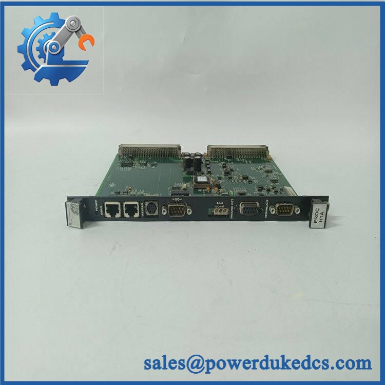
GE IS200EXHSG3REC
Module 5: Quality Assurance & Testing SOP
A strict pre-shipment inspection for GE IS200EXHSG3REC should include:
- Identity verification: Confirm the complete IS200EXHSG3REC catalog number, EXHS functional acronym, G3 group, revision markings, serial information, and connector arrangement.
- OEM anti-counterfeit visual inspection: Examine GE board markings, PCB artwork, relay identification, terminal construction, solder quality, components, and evidence of unauthorized modification.
- Mechanical inspection: Check mounting points, connector interfaces, relay sockets, card surfaces, wiring interfaces, and PCB condition for cracks, corrosion, contamination, or physical damage.
- Relay inspection: Verify the K53A, K53B, and KDEP relay assemblies and inspect relay sockets and retaining clips.
- Power-on self-test (POST): Install the board in an approved EX2100 test arrangement and verify normal startup and diagnostic behavior.
- 125 VDC contact-path test: Verify the standard-contactor power path under controlled conditions. GE specifies 125 VDC nominal, 140 VDC maximum for the relevant relay contact circuits.
- K53A/K53B relay test: Exercise both field-flashing pilot relay paths and verify expected switching behavior.
- KDEP relay test: Verify de-excitation pilot-relay operation and status transfer.
- K41A/K41B driver test: Exercise the standard-contactor driver paths and confirm correct 125 VDC output behavior.
- Contact-input test: Simulate the 41, 53A, and 53B auxiliary-contact feedback signals and verify correct acquisition.
- EDEX interface test: Verify de-excitation and crowbar status signal paths from the associated EDEX/EXDE circuitry.
- M1/M2/C interface test: Test the redundant controller connections and confirm correct command and feedback routing.
- Relay load testing: Apply controlled representative loads to applicable relay outputs while monitoring voltage, current, contact stability, and temperature.
- Timing test: Verify the expected high-speed contactor response and dropout behavior where the approved test fixture supports it.
- Extended run test: Cycle relay and contactor-control functions repeatedly while monitoring for intermittent operation, excessive heating, or unstable feedback.
- Final QC: Record serial number, revision, relay-test results, 125 VDC measurements, M1/M2/C interface results, condition grade, photographs, and packaging approval.
GE specifies that on EXHSG3/4 boards the current-regulator circuit used on G1/G2 is omitted and the driver provides a constant P125 voltage to the coil. That distinction should be explicitly checked during testing rather than assuming all EXHS boards use the same drive method.
Module 6: Procurement & Lifecycle FAQ
Is GE IS200EXHSG3REC genuinely in stock, and what is the cutoff for emergency shipping?
Physical inventory should be confirmed against the exact IS200EXHSG3REC marking before PO release. Emergency dispatch depends on verified physical stock, payment clearance, export documentation, and the carrier’s daily pickup cutoff.
How do you verify the condition and authenticity of this legacy EXHS board?
Require complete catalog-number and serial verification, OEM marking inspection, PCB and relay examination, power-up diagnostics, K53A/K53B/KDEP relay testing, K41 driver testing, contact-input verification, controller-interface testing, and documented final QC.
Can I replace with another EXHS board?
Not automatically. GE defines four EXHS functional groups according to contactor type and control architecture. G3 is the redundant configuration for standard 125 VDC contactors; G1 uses a different high-speed contactor arrangement, while G2/G4 are simplex variants.
Are there firmware compatibility issues I should warn my engineers about before issuing the PO?
Firmware is not normally the primary concern for this relay-driver PCB. The critical checks are the G3 redundant architecture, 125 VDC standard-contactor interface, M1/M2/C connections, relay assignments, 41/53A/53B feedback paths, and associated EDEX/EXDE signals. GE’s replacement procedure also requires the equipment to be fully de-energized and all cables correctly identified before removal.
What warranty and return terms should procurement require?
The quotation should specify the exact part number, revision, condition grade, serial traceability, relay and driver test scope, warranty period, DOA coverage, and return authorization procedure. For an excitation-control board, the acceptance record should retain the actual relay switching, 125 VDC, and controller-interface test results tied to the supplied unit.











 Start Chat


