

Description
- Brand: GE Industrial Systems
- Full Model Number: IS200ISBBG2AAB
- Lifecycle Status: Legacy / Lifecycle-managed
- Core Function: InSync Bus Bypass Board for GE EX2100 excitation control
- Top 3 Technical Specs: ISBB functional acronym; EX2100 Series Group 2 board; normal PCB coating with A/A functional revisions and B artwork revision
- Stock & Condition: New Surplus / Tested Refurbished; Physical stock confirmation required; Emergency dispatch subject to order cutoff
The IS200ISBBG2AAB is identified as an InSync Bus Bypass Board, abbreviated ISBB, for the GE EX2100 excitation-control family. Available technical references identify the board as a Group 2 EX2100 assembly with two A-rated functional revisions and B-rated artwork revision. It uses normal PCB coating and has four external connection points, including a two-position terminal block and three right-angle plug connectors.
Module 3: Obsolescence & Supply Chain Deep Dive
A failed IS200ISBBG2AAB can interrupt the intended InSync bus-bypass path inside an EX2100 excitation system, creating a hardware-availability problem even when the primary regulator and other control boards remain serviceable. The board is specifically identified as an ISBB InSync Bus Bypass assembly rather than a general-purpose I/O card. Its hardware includes relays, LED indicators, jumper switches, rectifier diodes, and multiple board-level connectors.
From a TCO standpoint, an exact replacement can preserve the existing EX2100 bus architecture, mounting arrangement, wiring, and installed control hardware. That avoids unnecessary cabinet redesign and a wider excitation-system migration. Revision control is the main procurement issue here: the IS200ISBBG2AAB is a revised form of the IS200ISBBG2 family, and the available technical reference identifies A/A functional revisions with B artwork revision. The replacement should therefore be matched against the complete board marking rather than only the ISBB acronym.
Module 4: Compatibility & Replacement Matrix
| Purchase Approval Item | Assessment |
|---|---|
| Replacement Classification | Drop-in Replacement for an identical IS200ISBBG2AAB installation |
| System Family | GE Excitation Control |
| Module Type | InSync Bus Bypass Board |
| Functional Acronym | ISBB |
| Board Group | |
| Functional Revision | A / A |
| Artwork Revision | B |
| PCB Coating | Normal Coating |
| Software Compatibility | No routine application software flash expected at board level; system configuration must be verified |
| Hardware Modification | Normally not required for an exact replacement |
| Estimated Physical Changeover | 30–90 minutes |
| Commissioning / Validation | Required for bus-bypass function, jumpers, LEDs, relays, and system integration |
Field Traps — Watch Out
- Revision mismatch: Do not approve another IS200ISBBG2 variant solely because the base number matches. The supplied IS200ISBBG2AAB carries two functional A revisions plus B artwork revision; complete board markings should be compared before installation.
- Jumper and relay configuration: The board incorporates jumper switches, relays, and LED indicators. Photograph the original jumper positions and wiring before removal, then reproduce the approved configuration during replacement.
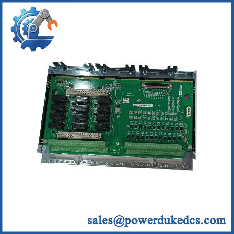
GE IS200ISBBG2AAB
Module 5: Quality Assurance & Testing SOP
The ISBB should be tested as a dedicated bus-bypass assembly, not merely powered on a bench.
- Incoming traceability: Record GE identification, complete number, serial information, functional revisions, and artwork revision.
- OEM anti-counterfeit visual inspection: Inspect GE markings, PCB labels, board construction, connector geometry, relay components, LED indicators, jumper switches, and evidence of unauthorized rework.
- Mechanical inspection: Verify mounting holes, connector alignment, terminal block condition, PCB edges, and retaining hardware.
- Power-on self-test (POST): Apply controlled test power and verify expected startup behavior and LED indications.
- Supply verification: Confirm correct board supply conditions and monitor current draw and temperature.
- Connector continuity test: Verify all applicable connector and terminal paths against the approved wiring reference.
- Jumper verification: Record and confirm jumper positions against the original board or approved engineering configuration.
- Relay test: Exercise installed relay circuits under controlled laboratory conditions and verify expected switching behavior.
- LED verification: Confirm each applicable status indicator responds correctly during normal and simulated fault conditions.
- Bus-bypass functional test: Simulate the relevant InSync bus condition and verify expected bypass behavior within the approved test setup.
- System-interface test: Verify interaction with the associated control hardware and communication paths.
- I/O load testing: Apply representative relay/interface loads while monitoring voltage stability, contact behavior, and board temperature.
- Extended operation: Run repeated bypass and recovery sequences while monitoring intermittent faults and status changes.
- Final QC release: Record board revision, jumper configuration, relay results, LED results, functional test results, inspection date, and technician approval.
Module 6: Procurement & Lifecycle FAQ
1. Is the GE genuinely in stock, and what is the cutoff for emergency shipping?
Current supplier listings show being offered as available, including listings that state in-stock status and same-day shipping. These are commercial listing claims, so emergency procurement should still require physical warehouse verification, exact board identification, condition confirmation, and the daily shipping cutoff before PO release.
2. How do you guarantee the condition and authenticity of this surplus bypass board?
Verification should begin with the complete marking and revision structure. Inspect the PCB, connectors, terminal block, relays, LEDs, jumper switches, mounting hardware, and evidence of previous repair. Functional testing should then confirm power-up response, relay operation, LED behavior, and InSync bus-bypass operation.
3. Are there any firmware compatibility issues I should warn my engineers about before issuing the PO?
There is no conventional firmware-flash requirement that defines the board’s basic function. The important engineering checks are board revision, jumper configuration, connector arrangement, architecture, and the approved InSync bypass logic. The A/A functional revision and B artwork revision should be documented before installation.
4. Can the replace the existing ISBB without hardware modification?
For an exact replacement in the same architecture, hardware modification is normally not required. Verify the mounting pattern, connector arrangement, terminal wiring, jumper positions, and associated boards before energizing the replacement.
5. What warranty and return terms should procurement require?
The PO should specify , exact revision, application, condition, jumper/configuration status, test results, warranty period, and return procedure. Warranty coverage should address DOA and verified board failure while excluding damage caused by incorrect installation, jumper errors, unsuitable power, wiring faults, ESD, or unauthorized modification.











 Start Chat


