

Description
- Brand: GE
- Full Model Number: IS200TRLYH1BHH
- System/Series Family: Mark VI / Mark VIe
- One-Sentence Core Function: Relay output terminal board providing 12 plug-in magnetic relay channels for solenoid actuation, dry-contact signaling, and turbine auxiliary control
- Top 3 Hardcore Specs: 12 plug-in magnetic relays; 48 barrier terminals; Form-C relay architecture
- Channel Configuration: Channels 1–6 configurable for solenoid drive or dry Form-C contact
- Dry Contact Channels: Channels 7–11
- Special Relay Channel: Channel 12
- Suppression: MOV suppression
- Feedback: Voted coil-drive feedback
- I/O Pack Interface: DC-37 connectors for PDOA/YDOA applications
- Redundancy: Simplex and TMR architectures
- Stock Status: New Surplus / Fully Tested Refurbished subject to availability
Module 3: Commercial-Technical Deep Dive
A failed TRLY board can turn a single output-path fault into a turbine-control maintenance event because the IS200TRLYH1BHH sits between the Mark VI or Mark VIe I/O architecture and the field relay circuits. This TRLY1B design provides 12 plug-in magnetic relay channels, with the first six channels capable of being configured for external solenoid drive or dry Form-C contacts. Channels 7 through 11 provide isolated Form-C contact functions, while channel 12 is designated for a specialized relay application. The board also incorporates voted coil-drive feedback, socketed sealed relays, MOV suppression, and 48 field terminals.
The channel structure is where the practical value lies. One board can handle multiple field-output requirements without forcing the control engineer to use a separate interface for every relay function. The first six channels can accommodate installation-specific solenoid-drive arrangements, including 125 VDC or 115/230 VAC supplies and an optional 24 VDC configuration, while the dry-contact channels avoid supplying field power internally. For Mark VIe installations, the board interfaces with the PDOA/YDOA I/O pack through DC-37 connections; simplex systems use JA1, while TMR configurations use JR1, JS1, and JT1. That connector assignment must be confirmed before wiring because a mechanically similar terminal board can have a different I/O-pack topology.
Module 4: Compatibility & Installation Traps
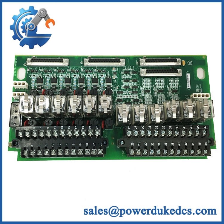
GE IS200TRLYH1BHH
Migration/Compatibility
- Primary Function: Relay output terminal board for GE Mark VI / Mark VIe turbine-control systems.
- Board Family: TRLY1B relay-output architecture.
- Relay Count: 12 plug-in magnetic relays.
- Mark VIe I/O Pack: Compatible with PDOA/YDOA I/O-pack arrangements.
- Simplex Wiring: JA1 is used for the I/O-pack connection.
- TMR Wiring: JR1, JS1, and JT1 are used for the three I/O-pack paths.
- Mark VI Compatibility: The TRLYH1B family is documented for Mark VI applications in conjunction with VCCC, VCRC, or VGEN interfaces.
- Logic Rewrite: Normally not required when replacing the same TRLY hardware in an unchanged control architecture, but the I/O-pack configuration and field wiring must be checked.
- Revision Matching: The requested IS200TRLYH1BHH should be matched against the installed board marking and system bill of materials rather than treating all TRLY revisions as electrically identical.
⚠️ Field Traps (Watch Out)
1. Do not treat all 12 relays as interchangeable outputs.
The channel groups have different intended functions. Channels 1–6 can be configured for solenoid driving or dry-contact operation, while channels 7–11 are standard dry Form-C outputs and channel 12 serves a specialized application. Verify the wiring drawing before moving field conductors.
2. Verify the I/O-pack connector assignment before insertion.
For Mark VIe simplex installations, JA1 is the specified I/O-pack connection; TMR arrangements use JR1, JS1, and JT1. A connector mismatch can create a complete output-path failure even when the replacement board itself is functional.
3. Check external field supply assumptions.
Solenoid-driver channels can use installation-specific external supply arrangements. Do not assume the board provides 24 VDC simply because a 24 VDC option exists. Confirm the actual jumper, fuse, suppression, and field-power configuration from the cabinet drawings before energizing.
Module 5: Quality Assurance SOP
Each available IS200TRLYH1BHH should pass a documented inspection and relay-output test before shipment:
- OEM anti-counterfeit visual inspection: Verify GE markings, complete catalog number, revision information, PCB layout, relay arrangement, connector positions, and terminal-block construction.
- Board identification check: Confirm the physical marking specifically identifies IS200TRLYH1BHH and document any additional board or assembly numbers.
- PCB condition inspection: Examine for corrosion, contamination, cracked components, damaged terminal blocks, bent connector pins, thermal discoloration, and previous repair evidence.
- Relay inspection: Check all 12 socketed magnetic relays for physical damage, loose seating, damaged pins, and abnormal mechanical condition.
- MOV inspection: Check suppression components adjacent to the relay-drive circuitry for cracking, discoloration, or evidence of surge damage.
- Power-on self-test (POST): Install the board in an approved GE Mark VI/Mark VIe test setup and verify expected controller-side status.
- Relay actuation test: Energize each relay through a controlled test fixture and verify mechanical switching.
- Form-C contact verification: Check NO, NC, and COM continuity for the applicable relay channels before and after actuation.
- Coil feedback verification: Verify the available coil-drive feedback path under the supported test configuration.
- Communication handshake verification: Where a compatible PDOA/YDOA test setup is available, establish the I/O-pack connection and verify command-to-relay response.
- TMR path test: For units designated for TMR service, verify the three applicable connector paths independently when the test rack supports JR1, JS1, and JT1.
- Suppression check: Inspect MOV-associated circuits after repeated controlled relay switching for abnormal heating or visible stress.
- Final QC record: Record catalog number, revision, relay test results, contact continuity measurements, I/O-pack test results, trace information, and technician sign-off.
- ESD-safe packaging: Place the board in ESD-safe packaging and mechanically protect the exposed terminal blocks and connectors.
The board-level design is particularly suitable for functional testing because the relay sockets, field terminals, and connector paths can be checked individually rather than relying solely on a powered visual inspection. The documented TRLY1B architecture includes 12 relay channels and 48 field terminals, making channel-by-channel verification worthwhile before shipment.
Module 6: CRO-Driven Buyer FAQ
Is the GE IS200TRLYH1BHH obsolete?
The IS200TRLYH1B family belongs to the legacy GE Mark VI / Mark VIe turbine-control architecture. It is still relevant where installed systems depend on the existing TRLY termination design, relay channel arrangement, and compatible I/O packs. For replacement procurement, the exact board suffix and installed system architecture should be verified before shipment.
How many relay outputs are on the ?
There are 12 plug-in magnetic relays. Their functions are not identical: channels 1–6 can be configured for solenoid-driver or dry Form-C operation, channels 7–11 provide dry Form-C contacts, and channel 12 is designated for a specialized application.
Can the be hot-swapped?
Do not assume field replacement under power is automatically permitted. The safe procedure depends on the installed Mark VI/Mark VIe architecture, I/O-pack configuration, and plant maintenance procedure. For a TMR system, the replacement sequence must also preserve the intended three-path architecture rather than treating the board like a generic plug-in relay card.
What should I verify before ordering the exact HHH version?
Confirm the complete designation, the installed I/O pack, simplex or TMR architecture, connector assignment, relay channel configuration, and field supply arrangement. For Mark VIe PDOA/YDOA installations, verify whether the existing system uses JA1 for simplex or JR1/JS1/JT1 for TMR.
What warranty and technical support should I expect?
Warranty duration should be stated for the actual unit condition and testing level on the quotation. Technical support should cover part-number verification, revision matching, relay-channel compatibility, connector assignment, installation guidance, and documented bench-test results. Production-system logic changes or turbine application engineering should be treated separately unless explicitly included.











 Start Chat


