

Description
- Brand: GE
- Full Model Number: IS210BPPCH1AC
- Product Type: BPPCH Bridge Personality / Interface Board
- System/Series Family: GE Mark VI
- Core Function: Bridge interface and signal-processing board used within the Mark VI control architecture
- Top 3 Hardcore Specs: Mark VI platform | BPPCH board designation | Revision AC
- Board Family: IS210BPPCH
- Hardware Revision: 1AC
- Stock Status: New surplus / condition to be confirmed per available unit
The GE IS210BPPCH1AC is part of the GE Mark VI BPPCH board family. The board is associated with bridge/interface functions within the Mark VI control architecture, where dedicated interface circuitry links control electronics with associated power or signal-processing sections. The complete IS210BPPCH1AC identification is important because Mark VI boards can have closely related part numbers with different revisions and functions.
Module 3: Technical Product Introduction
A bridge-interface board sits between critical control circuitry and the hardware it supervises, so a failure can produce symptoms that look like a controller, communication, or power-stage problem. GE IS210BPPCH1AC belongs to the Mark VI BPPCH board family and is intended for interface functions within the control system. When troubleshooting a failed board, the first step should be to identify exactly which interface signals are missing rather than replacing unrelated Mark VI modules.
For this board, the IS210BPPCH1AC designation should be treated as the primary procurement identifier. Exact electrical ratings, connector assignments, signal types, and board-level functions should be confirmed from the applicable GE documentation for the installed revision rather than inferred from the BPPCH prefix alone. —Mark VI boards with similar physical formats are not necessarily interchangeable, even when they occupy comparable cabinet locations.
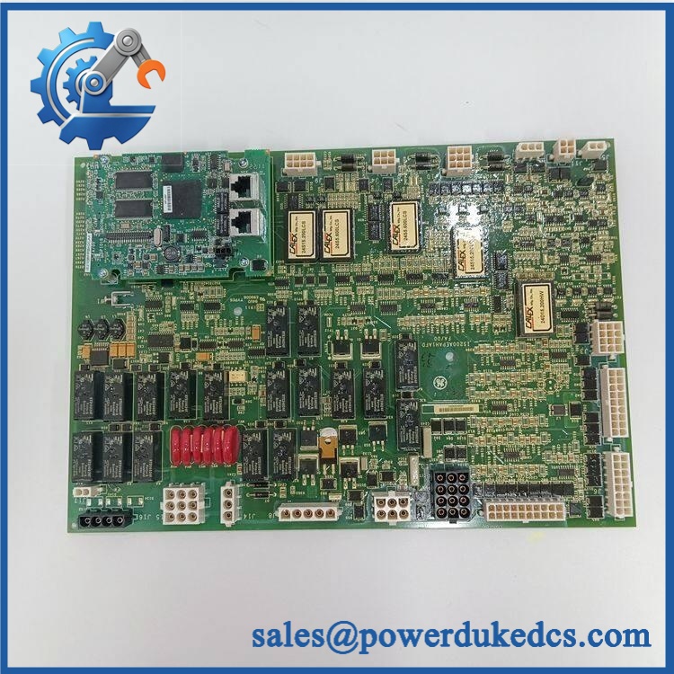
GE IS210BPPCH1AC
Module 4: Application Scenarios & Field Realities
- Within GE Mark VI turbine-control cabinets, the BPPCH board can form part of the interface chain between control electronics and associated bridge/power circuitry. A replacement should therefore be evaluated together with its mating boards and connected harnesses.
- When a bridge-related diagnostic appears, inspect the board connectors, ribbon cables, terminal interfaces, and associated power supplies before condemning the PCB. A poor connection can create the same symptoms as an electronic failure.
- During planned Mark VI maintenance, record the board’s complete part number and revision before removal. Photograph connector locations and cable routing; this reduces the risk of reversing a harness during reinstallation.
- For intermittent faults, check cabinet temperature and vibration conditions in addition to electrical continuity. A board that works during a short bench test can still have a marginal connector or thermally sensitive component that only fails after sustained operation.
Module 5: Migration, Compatibility & Installation Traps
Replacement Matrix
| Replacement Type | IS210BPPCH1AC Assessment |
|---|---|
| Drop-in Replacement | Potentially yes, when replacing the same revision in a compatible Mark VI installation |
| Software Compatible | Configuration-dependent; verify the associated Mark VI control configuration and board identification |
| Hardware Modification Required | Not expected for an exact replacement; required if connector, revision, or electrical interface differs |
Field Traps — Watch Out
1. Do not substitute by the BPPCH prefix alone.
The complete part number and revision must match the installed board or an approved GE replacement reference. Similar Mark VI boards can have different connector layouts or circuit functions.
2. Inspect mating hardware before replacement.
Check connectors, ribbon cables, terminal interfaces, and associated boards for bent contacts, oxidation, contamination, or mechanical damage. Replacing the PCB without correcting a damaged interface can reproduce the original fault.
3. Verify cabinet power isolation.
Mark VI control cabinets can contain multiple power domains. Isolate the applicable sources and verify absence of hazardous voltage before removing the board.
4. Control ESD exposure.
Handle the board only using an appropriate ESD procedure. Avoid touching connector contacts or exposed circuitry during installation.
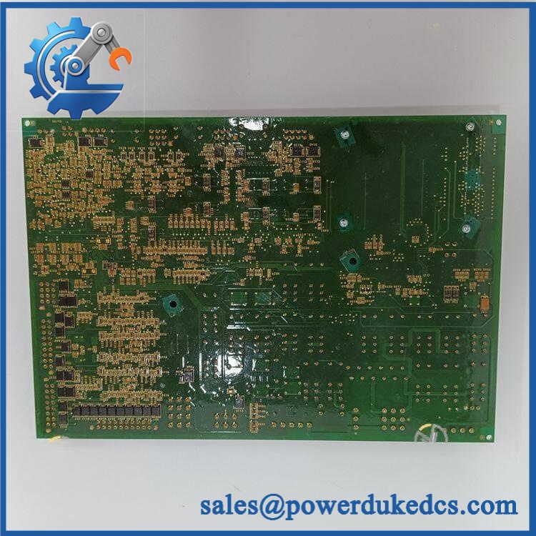
GE IS210BPPCH1AC
Module 6: Quality Assurance SOP
Before shipment, each available should pass a documented inspection sequence:
- OEM identification inspection — Verify GE markings, complete designation, board labels, revision information, and serial/lot markings where available.
- OEM anti-counterfeit visual inspection — Examine PCB construction, component markings, connector workmanship, labels, solder joints, and evidence of unauthorized modification.
- Physical inspection — Check the PCB, mounting points, connector interfaces, board edges, and exposed components for cracks, corrosion, contamination, or mechanical damage.
- Part-number verification — Match the physical board against the customer’s exact requirement before testing.
- Power-on self-test (POST) — Where a compatible Mark VI test environment supports board diagnostics, apply the specified power and verify normal initialization without board-related faults.
- Interface continuity verification — Test applicable signal paths and connector interfaces against the approved test procedure.
- Functional simulation — Where suitable Mark VI test equipment is available, simulate representative bridge/interface signals and verify the board’s response.
- Communication/interface verification — Confirm that the installed test system recognizes the board and that applicable signal exchange occurs correctly.
- Diagnostic verification — Check for abnormal hardware status, board faults, unexpected signal states, or intermittent behavior.
- Extended stability test — Operate the board under controlled conditions and monitor for thermal drift, resets, signal loss, or intermittent interface faults.
- Final visual inspection — Recheck labels, connectors, mounting features, and PCB condition after testing.
- Test record and packaging — Record the part number, revision, test results, inspection date, and packaging condition before dispatch.
QA note: BPPCH is an interface board rather than a standalone PLC CPU. A generic RUN/ERR LED POST claim should not be made unless the exact board revision provides those diagnostics. Board identification, connector/interface testing, controlled signal simulation, and Mark VI system recognition are the more meaningful acceptance checks.











 Start Chat


