

Description
- Model: IS215ACLEH1A
- Brand: GE General Electric
- Series: EX2100 Excitation Control / Innovation Series
- Part Type: Application Control Layer Module
- Functional Designation: ACLE
- Assembly Level: 215, higher assembly with additional components
- Mounting Format: 2-slot, 6U VME rack
- Processor: Pentium P5 266 MHz PC/104-Plus processor assembly
- Memory: 128 MB DRAM; 256 KB L2 cache
- Storage: 16 MB CompactFlash nonvolatile storage reported for the carrier architecture
- Communication: 2 × Ethernet ports; 2 × RS-232 COM ports
- Operating System: QNX real-time operating system
- Status LEDs: Active, OK, ENET, Status, Flash
- Front Controls: Reset switch
- Approx. Board Dimensions: About 159 × 102 mm for the referenced board envelope; complete 6U assembly dimensions should be verified before freight booking
- Estimated Shipping Weight: Secondary inventory records vary from approximately 0.14 kg to 0.52 kg; use the actual packed assembly for freight calculations
- What’s in the Box: IS215ACLEH1A module only unless the PO specifically includes serial adapters, cables, removable storage, or documentation
- Optional Cables: GE records commonly associate 336A4929G1 and 336A3582P1 serial cables with this module
- Packaging: ESD shielding bag, rigid support, faceplate protection, moisture barrier, shock-resistant carton
GE-related technical records identify IS215ACLEH1A as an Application Control Layer Module for EX2100, with two Ethernet ports, two serial ports, a 6U VME mounting format, and GEI-100434 / GEH-6632 documentation references.
Product Introduction
Structure B — Architecture Hook
The GE IS215ACLEH1A sits at the application-control layer of the EX2100 excitation system, mounted in the standard control rack as a two-slot, 6U VME module. Its controller hardware provides application processing, Ethernet communication, serial interfaces, and nonvolatile storage for the excitation-control environment. GE-related service records identify it as a microprocessor-based control module rather than a conventional I/O card.
From an asset-management standpoint, preserve the complete assembly identity. The IS215ACLEH1A is associated with GEI-100434 and GEH-6632, and later revisions such as IS215ACLEH1AB and IS215ACLEH1AC appear in the same family. A replacement therefore requires more than matching the front label; processor configuration, RAM, CompactFlash contents, backplane compatibility, firmware, and application software all deserve verification before commissioning (important when maintaining an older EX2100 installation).
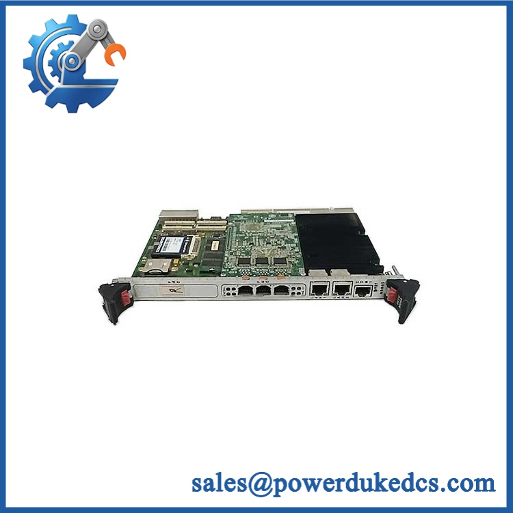
GE IS215ACLEH1A
Core Technical Specifications
| Parameter | Value |
|---|---|
| Manufacturer | GE General Electric |
| Part Number | IS215ACLEH1A |
| Series | EX2100 Excitation Control |
| Board Designation | ACLE |
| Product Type | Application Control Layer Module |
| Mounting Format | 2-slot, 6U VME |
| Processor | Pentium P5, 266 MHz, PC/104-Plus architecture |
| Alternative Processor Records | Intel 486, 100 MHz appears in some historical records; verify the actual board configuration |
| L2 Cache | 256 KB |
| DRAM | 128 MB, expandable according to cited technical records |
| Nonvolatile Storage | 16 MB CompactFlash reported for the processor/carrier architecture |
| Operating System | QNX real-time OS |
| Ethernet | 2 × 10BaseT Ethernet |
| Serial Interfaces | 2 × RS-232, COM1/COM2 |
| Application Role | Excitation/control application processing |
| Associated Backplanes | IS200ESBP, IS200EBKP, IS200ERBP, IS200ERRB |
| LEDs | Active, OK, ENET, Status, Flash |
| Front Reset | Yes |
| Power Input | 5 VDC through the backplane |
| Power Draw | Configuration-dependent; no reliable standalone value established |
| Heat Dissipation | Processor, memory, storage, and rack airflow dependent |
| Memory Limits | 128 MB DRAM documented; exact maximum expansion depends on installed SODIMM/carrier configuration |
| Firmware | BIOS / QNX / application-code dependent |
| Dimensions | Approx. 159 × 102 mm board reference; complete module depth must be verified |
| Weight | Secondary records vary materially; physical weighing recommended |
| Lifecycle Profile | Legacy / largely obsolete EX2100 hardware |
There is conflicting historical data on the exact processor fitted to all assemblies. Some records identify a 486 at 100 MHz, while others specify a Pentium P5 at 266 MHz with a PC/104-Plus board, 128 MB DRAM, and 256 KB L2 cache. The actual hardware revision and internal PC/104 assembly should therefore control the receiving record.
🚨 Global Compliance & Industry Certifications
- CE Mark: May apply to the complete equipment configuration. Do not make a standalone CE claim for the PCB or controller module without the applicable GE declaration.
- UL/cUL: Verify the exact cabinet and hardware configuration before recording UL or cUL status.
- ATEX / IECEx: Do not assume hazardous-area approval for itself. The complete excitation system, enclosure, field interfaces, and installation determine hazardous-area suitability.
- Marine Approvals: No revision-specific DNV approval was established for this exact ACLE module from the accessible records.
- Electrical Safety: The module is installed in a powered VME control rack. The backplane can remain energized even when external process equipment appears stopped.
- EMC: Ethernet, serial, and VME interfaces make grounding and cable routing important for electromagnetic compatibility at the complete cabinet level.
- Functional Safety: Do not assign a standalone SIL rating to ACLE. Any safety claim belongs to the engineered excitation/control architecture.
- Audit Documentation: Retain the exact part number, revision, processor/memory configuration, CompactFlash identification, serial number, COO, test report, and applicable conformity documents.
Verify specific lot certifications with OEM.
🚨 Long-Term Storage & Asset Preservation Guide
Protect the removable storage components. The ACLE architecture uses nonvolatile storage, and the exact CompactFlash contents can be critical to application startup. Do not casually replace or reformat the storage device on shelf inventory. Record the media identification and software/configuration revision at receiving.
Keep the module in ESD shielding packaging. The VME connector, PC/104-Plus electronics, DRAM, Ethernet interfaces, and serial circuitry should remain isolated from uncontrolled static exposure. Use connector protection and rigid support around the metal faceplate.
Control humidity and condensation. A clean indoor warehouse below roughly 60% RH is a practical preservation target when the OEM storage specification is unavailable. Use sealed packaging with suitable desiccant and inspect connector contacts for oxidation during periodic audits.
Do not repeatedly power-cycle shelf stock. For legacy processor modules, capture the last qualified test date, BIOS/software revision, memory size, storage media identity, and packaging condition. A controlled functional test before deployment is preferable to casual energized inspection.
Physical Installation Prerequisites
- Rack Format: Install in the correct 2-slot, 6U VME control rack.
- Backplane: Verify the specific supported backplane before insertion. Historical records identify IS200ESBP, IS200EBKP, IS200ERBP, and IS200ERRB families.
- Power: The module receives 5 VDC through the backplane; verify rack power quality before insertion.
- Processor/Memory: Record the original processor, DRAM size, BIOS version, and CompactFlash identity before replacement.
- Ethernet: Confirm ENET1/ENET2 cable assignments and network topology.
- Serial: Verify COM1/COM2 wiring and the correct serial adapter cable.
- Grounding: Secure the metal faceplate and verify rack protective bonding before startup.
- Cooling: Maintain unobstructed VME rack airflow. Keep cable bundles away from heat-producing processor areas.
- Clearance: Allow enough front access to operate the reset switch and observe all five diagnostic LEDs.
- ESD: Use a grounded wrist strap and ESD-safe workstation when removing the module from its shielding bag.
- Cable Strain: Do not allow Ethernet or serial cable weight to load the front-panel connectors.
- Commissioning: After installation, verify BIOS startup, QNX boot behavior, Ethernet status, serial communications, application download, and controller handoff before enabling the excitation system.
The front-panel Active, OK, ENET, Status, and Flash indicators provide useful startup evidence; record their states during the replacement test rather than relying only on software diagnostics.
Buyer’s FAQ
Q1. What HS tariff code should be used for GE ?
Do not classify the unit simply as a generic PCB. is a microprocessor-based application control module used in an excitation-control rack. A provisional review may consider classifications covering parts of electrical control equipment, but the final national tariff code depends on the importing jurisdiction and the exact commercial function.
For the commercial invoice, use a precise description such as “GE Application Control Layer Module” and have the importer or customs broker confirm the final HS classification.
Q2. What Country of Origin should appear on the COO?
Use the actual manufacturing origin of the physical module, supported by the nameplate and supplier traceability. Some secondary records identify the United States, but that should be verified against the actual serial-numbered asset before the COO is issued.
Keep the physical-unit photograph, serial/date-code record, supplier COO statement, and commercial invoice together.
Q3. Should I insure shipment of ?
Yes, when it is a critical excitation-system spare. Protect the VME card edge, front faceplate, CompactFlash area, and connectors against impact and electrostatic damage.
Photograph the complete module, part number, revision, processor/storage area, serial number, and packaging before dispatch.
Q4. Does include the latest firmware pre-loaded?
Do not assume it does. The module contains firmware-bearing and operating-system components, while application code and configuration are system-specific. The replacement should be checked for BIOS version, QNX environment, DRAM configuration, CompactFlash contents, and application software before commissioning.
Q5. Can replace IS215ACLAH1A directly?
They should not be treated as universally identical without engineering review. GE-related records describe ACLE as a later Application Control Layer architecture and identify IS215ACLAH1A as an earlier ACLA family member. The two serve related application-control roles, but the rack, backplane, processor architecture, software image, and physical format must be checked before considering substitution.











 Start Chat


