

Description
- Brand: GE
- Full Model Number: IS400TRLYS1B
- Functional Family: TRLY
- System/Series Family: GE Mark VIeS
- One-Sentence Core Function: Relay output terminal board for Mark VIeS safety applications, interfacing YDOA I/O packs with field relay circuits
- Top 3 Hardcore Specs: Simplex or TMR architecture; 12 plug-in magnetic relays; individual relay-circuit integrity feedback
- I/O Pack Compatibility: YDOA Safety Relay Output I/O Pack
- Stock Status: New Surplus / Fully Tested Refurbished subject to actual inventory inspection
Module 3: Commercial-Technical Deep Dive
A failed relay terminal board can disable alarm, solenoid, interlock, or other discrete output functions while the Mark VIeS controller itself remains operational. The GE IS400TRLYS1B is the TRLY relay output terminal board used in the Mark VIeS architecture. Available technical references identify it as a relay-output board for Simplex or TMR configurations, with the YDOA I/O pack mounted directly on the terminal board. The board also provides integrity feedback on each relay circuit, allowing the control system to detect output-circuit health rather than treating a relay as a simple dry contact.
The practical value is maintaining the existing safety-output architecture without changing the Mark VIeS control application. One technical reference describes the TRLYS1B assembly as holding 12 plug-in magnetic relays, with the first six relay circuits configurable by jumpers for either dry Form-C contacts or external-solenoid control; an optional 24 VDC field-supply arrangement is also described. GE’s Mark VIeS system documentation lists IS400TRLYS1B among the replacement terminal boards associated with the safety relay-output I/O architecture. Exact field-output loading and jumper configuration remain installation-specific, so the cabinet drawing and original board setup should govern any replacement decision.
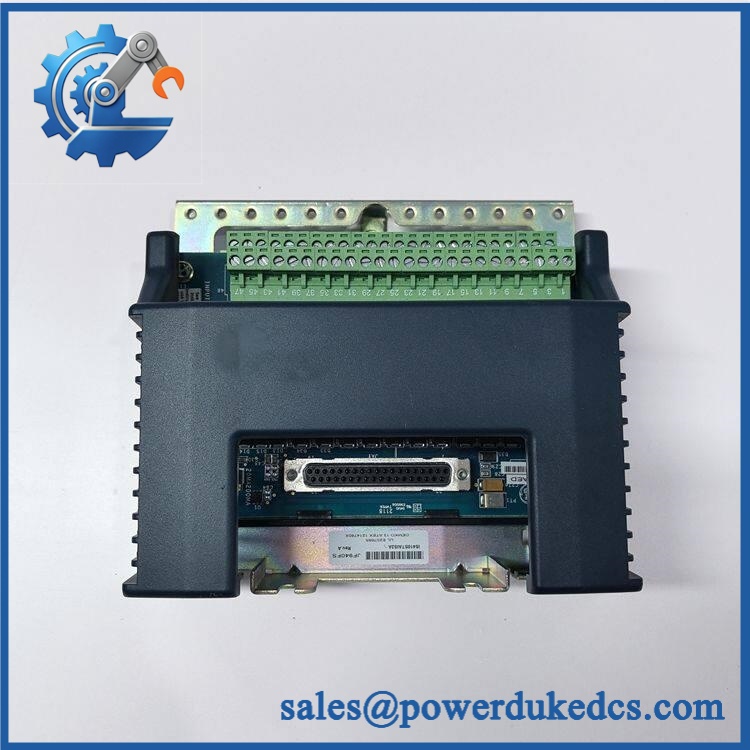
GE IS400TRLYS1B
Module 4: Compatibility & Installation Traps
Migration/Compatibility
- Replacement status: GE Mark VIeS TRLY relay output terminal board
- Logic rewrite: Normally not required for a like-for-like terminal-board replacement when the existing Mark VIeS project and YDOA configuration are retained.
- Firmware flash: Not applicable to the passive terminal board itself.
- Drop-in status: Potentially direct when the complete board revision, YDOA I/O pack, relay configuration, jumper settings, and field wiring match.
- Architecture: Designed for Simplex or TMR relay-output arrangements.
- I/O pack: The YDOA Safety Relay Output I/O Pack mounts directly to the TRLY terminal board.
- Revision caution: GE lifecycle documentation distinguishes newer IS400 terminal boards from earlier IS200 boards. Verify mounting and exact revision before substituting an older TRLY assembly.
⚠️ Field Traps (Watch Out)
- YDOA compatibility: Do not install a different Mark VIe/Mark VIeS I/O pack simply because the connector arrangement appears similar. The TRLY board is specifically associated with the YDOA safety relay-output pack.
- Jumper configuration: The first six relay circuits can be configured for different field-output arrangements. Record jumper positions before removing the original board; the replacement must reproduce the original output architecture.
- TMR wiring: In TMR applications, preserve the correct R/S/T channel assignment and field wiring. A physically correct board with incorrectly routed redundancy wiring can create output disagreement or diagnostic faults.
- Relay-circuit integrity: The board provides integrity feedback, so an incorrect field-side termination can generate a diagnostic even when the mechanical relay itself operates normally.
- Field energy: Relay terminals may be connected to externally powered solenoids, alarms, or interlocks. Isolate all relevant field supplies before removing the board.
Module 5: Quality Assurance SOP
Before shipment, the GE IS400TRLYS1B should undergo a relay-output-specific inspection sequence:
- OEM anti-counterfeit visual inspection — verify GE markings, IS400TRLYS1B identification, TRLY designation, PCB markings, terminal layout, relay arrangement, and connector geometry.
- Revision verification — confirm the complete board number and compare the physical revision against the requested installation.
- Mechanical inspection — inspect terminal connectors, relay sockets, mounting points, daughter interfaces, PCB surfaces, and retention hardware for impact, corrosion, contamination, or unauthorized modification.
- YDOA interface inspection — verify the I/O-pack mounting interface and connector condition before functional testing.
- Jumper verification — document every applicable field-output jumper position before energization.
- Controlled power-up — use an approved Mark VIeS test assembly and verify expected board status and relay initialization.
- Power-on self-test (POST) — confirm that the associated YDOA pack initializes correctly and that no terminal-board diagnostic faults are reported.
- Relay actuation verification — command each available relay channel under controlled conditions and verify consistent pickup and release.
- Contact-state verification — measure the appropriate NO/NC or configured field-output contacts using calibrated test equipment.
- Circuit-integrity verification — confirm the expected relay-circuit feedback and diagnostic behavior for representative healthy and faulted conditions.
- Simplex/TMR verification — where the test platform supports it, verify the configured redundancy architecture and correct relay-channel assignment.
- Final QC record — document exact part number, relay count, jumper settings, YDOA configuration, test results, photographs, and packaging condition.
For a safety relay terminal board, a relay-click test is not enough. Correct YDOA initialization, relay actuation, contact-state measurement, circuit-integrity feedback, and redundancy-channel verification are the meaningful acceptance checks.
Module 6: CRO-Driven Buyer FAQ
1. Is GE IS400TRLYS1B obsolete, and how do I verify an authentic replacement?
The is identified in current technical references as a GE Mark VIeS TRLY relay-output terminal board, and GE system documentation lists it within the Mark VIeS replacement architecture. For procurement, verify the exact marking, board revision, relay configuration, and YDOA compatibility rather than ordering against “TRLY” alone.
2. Can I hot-swap the ?
Do not assume hot-swap capability. Whether an online replacement is permitted depends on the specific Mark VIeS redundancy architecture and approved maintenance procedure. Isolate the applicable electrical and field-output sources and follow site LOTO requirements before removing the terminal board.
3. Does replacing the TRLY board require reprogramming the Mark VIeS controller?
Normally no complete application rewrite is required for a like-for-like terminal-board replacement. The key commissioning tasks are restoring the correct YDOA association, jumper configuration, relay-channel assignments, and field wiring, followed by verification of circuit-integrity diagnostics.
4. How many relays are on the ?
A technical reference for the TRLYS1B identifies 12 plug-in magnetic relays and describes configurable arrangements for the first six relay circuits. The actual field utilization depends on the Mark VIeS safety application and installed configuration.
5. What warranty and technical support are available?
Warranty duration should be stated according to the actual inventory condition, such as new surplus or tested refurbished. Technical support should cover exact board identification, YDOA compatibility, jumper-setting review, relay-output testing, integrity-feedback verification, and documented pre-shipment QA. Safety-system configuration, field rewiring, and live turbine commissioning remain the responsibility of qualified site personnel.











 Start Chat


