

Description
- Model: IS420UCSCS2A-B-V0.1-A
- Base GE Part Number: IS420UCSCS2A
- Brand: General Electric (GE)
- Series: Mark VIeS Functional Safety System
- Part Type: UCSC Safety Controller
- Core Function: Executes Mark VIeS safety-control logic and coordinates distributed I/O across the R/S/T IONet architecture.
- Processor: Dual-core 1.6 GHz AMD G-Series
- Memory: 2 GB DDR3-1066 ECC SDRAM
- Storage: 128 GB solid-state drive
- Control Execution: 10, 40, 80, or 160 ms frame rates, with synchronization across controllers in Dual and TMR configurations.
- Safety Role: GE identifies IS420UCSCS2A as the Mark VIeS Safety Controller, compliant with IEC 61508, and configurable in Simplex, Dual, and TMR architectures.
- Configuration Note: The appended “-B-V0.1-A” should be retained as part of the physical asset identity; the public GE specification identifies the base orderable/controller as IS420UCSCS2A.
Product Introduction
At the center of a Mark VIeS safety architecture sits the IS420UCSCS2A. This controller executes the application logic used for functional-safety loops, communicates with distributed Mark VIeS I/O packs through three IONet paths, and supports Simplex, Dual, and TMR controller arrangements. GE specifies a dual-core 1.6 GHz AMD G-Series processor, 2 GB ECC memory, and a 128 GB SSD.
The full marking IS420UCSCS2A-B-V0.1-A should be preserved in purchasing and maintenance records rather than shortening the identifier to “UCSC.” That matters during legacy migration and New Surplus qualification because the controller hardware, software baseline, safety configuration, and controller role all need to match the installed Mark VIeS system. GE currently lists the base IS420UCSCS2A as Active.
Core Technical Specifications
| Parameter | Value |
|---|---|
| Manufacturer | General Electric (GE) |
| Full Marking | -B-V0.1-A |
| Base Part Number | |
| Product Name | Mark VIeS Safety Controller |
| Series | Mark VIeS Functional Safety System |
| Safety Classification | IEC 61508 compliant |
| Redundancy | Simplex, Dual, TMR |
| Microprocessor | Dual-core AMD G-Series |
| Processor Frequency | 1.6 GHz |
| System Memory | 2 GB DDR3-1066 SDRAM |
| Memory Protection | ECC |
| Mass Storage | 128 GB SSD |
| Non-Volatile SRAM | No |
| IONet Ports | 3 |
| IONet Architecture | R / S / T |
| Controller Communications | EGD / UDH to ToolboxST PC, HMIs, UCSCH1B gateway, and GE PACSystems |
| Modbus TCP | Slave, read-only |
| Safety Controller-to-Controller Communication | Black Channel supported |
| Programming Languages / Methods | Function Block Diagram, Relay Ladder Diagram, Cause and Effect Matrix |
| Control Logic Frame Rates | 10, 40, 80, 160 ms |
| Input Voltage | 18–30 VDC |
| Nominal Input | 28 VDC |
| Maximum Input Power | 30.8 W |
| Power Connector | Phoenix Contact MC 1,5 / 3-STF-3,81 |
| Cooling | Convection |
| Mounting | Base-mounted |
| Controller Dimensions | 168 × 150 × 55 mm |
| Dimensions with Mounting Base | 204 × 152 × 55 mm |
| Weight | 1,327 g |
| Operating Ambient | -40°C to +70°C |
| Storage Temperature | -40°C to +85°C |
| Humidity | 95% non-condensing |
| G3 Compliance | Yes |
| Hazardous Locations | Class 1 Div. 2 / Class 2 Zone 2 / ATEX |
GE’s technical specification gives 30.8 W maximum input power, so this controller should be included explicitly in cabinet heat-load and 24/28 VDC power-budget calculations rather than treated as a negligible electronic load.
The controller is base-mounted and convection-cooled. GE specifies 25 mm clearance for the ambient-temperature reference used in its controller documentation; cabinet layout therefore has a direct relationship to the published temperature envelope.
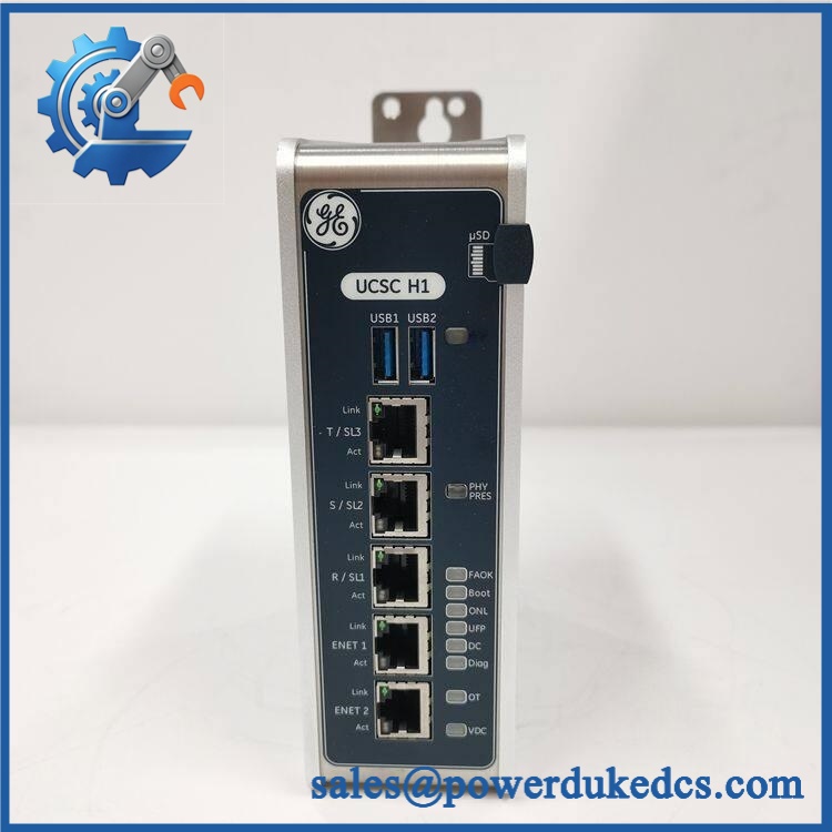
GE IS420UCSCS2A-B-V0.1-A
Application Scenarios & Pain Points
In a turbine safety application, the UCSCS2A serves as the computational platform for functional-safety logic rather than as a conventional field I/O module. Its Dual and TMR capability allows the controller architecture to be matched to the required safety design.
For a TMR installation, three synchronized controller paths can be used with R/S/T IONet communications. GE specifically states that frame execution is synchronized across controllers in Dual and TMR configurations.
At a cabinet temperature near 65°C, the thermal margin should be checked before replacement. The documented operating envelope reaches 70°C, but only with the specified installation conditions and clearance around the controller.
During a controller migration, the storage architecture becomes relevant. A 128 GB SSD provides substantial non-volatile storage, but a replacement controller still requires validation of the approved safety application image and engineering configuration. Hardware identity alone does not restore the site’s functional-safety application.
For power-generation and other safety-instrumented installations, one tested spare can be strategically important. A controller failure can become a prolonged outage when the replacement is physically correct but lacks the approved software/configuration baseline.
Common Error Codes & Diagnostic Symptoms
Symptom/Code: BOOT or startup sequence does not complete
→ Diagnosis: Possible power instability, storage/application-image issue, controller hardware fault, or software/configuration problem. GE identifies dedicated Power, Boot, Online, Ethernet, and Diagnostics indicators on the UCSC.
→ Action: Verify the 18–30 VDC input, startup indicators, storage health, and approved application image before replacing the controller.
Symptom/Code: DIAGNOSTICS indicator remains active
→ Diagnosis: A controller, software, IONet, or hardware-configuration diagnostic may be present. A red or active diagnostic indication alone does not prove processor failure.
→ Action: Read the actual Mark VIeS ControlST diagnostic message, verify controller identity, and isolate the fault before replacement.
Symptom/Code: IONet communication loss on R/S/T
→ Diagnosis: Possible network infrastructure, fiber/copper path, controller interface, power, configuration, or I/O-pack problem. GE specifies three IONet ports for R/S/T I/O communications.
→ Action: Test each network path separately and compare the controller’s health status with the redundant system path.
GE’s public UCSC documentation does not provide one universal numeric error-code table for every Mark VIeS installation. The exact alarm text and numeric identifier should be taken from the site’s ControlST diagnostic database.
Cross-Reference & Lifecycle Migration
Base Part Number
The authoritative GE specification identifies:
— Mark VIeS Safety Controller
The user’s complete marking IS420UCSCS2A-B-V0.1-A should be retained as the physical configuration identifier. GE’s orderable replacement part number remains .
Related UCSC Controller
A major source of purchasing error is confusion with:
IS420UCSCH1B — Mark VIe Gateway Controller
The H1B is a different controller. GE specifies it as a non-safety gateway with a quad-core 1.2 GHz AMD G-Series processor, while the UCSCS2A is the IEC 61508 safety controller with a dual-core 1.6 GHz processor. These are not equivalent substitutions.
Earlier / Alternative Controller Generations
The UCSC family also appears in Mark VIe/Mark VIeS documentation with other processor generations. Do not approve substitution merely because the front-panel form factor is similar. Safety role, firmware, application compatibility, and certification status must all be considered.
Firmware and Application Image
The UCSCS2A is configured through ToolboxST. GE specifies FBD, RLD, and Cause-and-Effect Matrix programming for the safety controller.
For a replacement unit, separate these two activities:
Hardware qualification — verify the exact controller identity, revision, and electrical specifications.
Application restoration — load or confirm the approved safety application and configuration baseline.
A New Original controller should therefore never be assumed to contain the exact safety logic currently running at the site.
Lifecycle Status
Status: Active. GE’s Mark VIeS specification explicitly lists as Active.
For inventory planning, this reduces the urgency associated with an immediate EOL buyout, but safety-critical sites should still maintain tested replacement stock because configuration recovery and safety validation can take substantially longer than physical procurement.
Field Engineer’s Tech Notes
Warning 1 — Do not use the gateway controller as a safety-controller substitute.
The IS420UCSCH1B and may look like members of the same UCSC family, but their system roles are materially different. One is a gateway/non-safety controller; the other is the Mark VIeS safety controller.
Warning 2 — Watch the power budget and cabinet temperature together.
At 30.8 W maximum input power, the controller contributes meaningful heat inside a compact enclosure. In a cabinet already operating near the upper end of its 70°C ambient specification, poor airflow can become a controller-reliability problem.
A third practical check is worth making: the UCSC has no batteries, no fans, and no hardware configuration jumpers. GE states that configuration is software-based, so do not waste troubleshooting time looking for a hardware DIP-switch setting that does not exist.
Strict QA & Testing SOP
Step 1 — Inbound identity inspection
Record IS420UCSCS2A-B-V0.1-A, base part number , serial number, revision markings, date code, and packaging information.
Step 2 — Physical examination
Inspect the enclosure, mounting base, power connector, Ethernet interfaces, status LEDs, ventilation openings, and mounting points. Check for corrosion, impact damage, contamination, or thermal discoloration.
Step 3 — Documentation reconciliation
Confirm that the unit is the Mark VIeS Safety Controller, not the UCSCH1B gateway controller. Record processor, memory, storage, and hardware-revision information.
Step 4 — Controlled power-up
Use a regulated supply within the specified 18–30 VDC input range. Observe Power, Boot, Online, and Diagnostic behavior during startup.
Step 5 — Controller self-test
Verify processor startup, memory initialization, SSD accessibility, and absence of persistent controller diagnostics.
Step 6 — IONet communications test
Connect the controller to an approved Mark VIeS test environment. Verify the appropriate R/S/T network paths and confirm expected communication with representative I/O hardware.
Step 7 — Safety application compatibility test
Confirm that the approved ToolboxST environment recognizes the controller correctly and that the intended safety application can be loaded or validated without hardware-identification conflicts.
Step 8 — Redundancy test
Where the test facility supports it, verify controller synchronization and the intended Simplex, Dual, or TMR configuration behavior. GE specifically supports all three configurations for .
Step 9 — Thermal observation
Operate the controller under representative load while monitoring temperature and cabinet airflow. The documented operating range is -40°C to +70°C, with installation-clearance conditions applying.
Step 10 — Final QA and packaging
Record test values, software/configuration identification, serial number, photographs, and technician sign-off. Package the controller in ESD-safe protection with mechanical cushioning. Test videos are available with the QC record for procurement verification.
Buyer’s FAQ
Q: Can I hot-swap the -B-V0.1-A?
A: Do not assume live replacement is acceptable. This is the Mark VIeS safety controller, and removing it can affect safety execution, network communications, and controller redundancy. Follow the site-approved safety maintenance procedure and establish the required safe state before disconnecting the controller.
Q: How do I verify a New Original unit?
A: Require photographs of the full marking, serial number, hardware revision, packaging labels, and connector condition. For a safety controller, also request the functional test report and traceability documentation. The base orderable number alone is not enough to establish the exact delivered configuration.
Q: Does this controller replace IS420UCSCH1B?
A: No. GE identifies as the IEC 61508 Mark VIeS Safety Controller and IS420UCSCH1B as the Mark VIe Gateway Controller. Their processor architecture and safety role differ, so substitution requires an approved system-engineering decision.
Q: What warranty should be required?
A: Specify DOA and functional-failure coverage tied to the controller serial number, together with pre-shipment test evidence. For a safety-critical controller, require clear documentation of the hardware revision and tested configuration so that a warranty return does not create a second compatibility problem.











 Start Chat


