

Description
- Brand: GE Multilin
- Full Model Number: MIFIIPI55E00HI00
- System/Series Family: GE Multilin MIF II Digital Feeder Protection Relay
- One-Sentence Core Function: Three-phase plus ground digital relay providing feeder overcurrent protection, metering, monitoring, and control
- Top 3 Hardcore Specs: 5 A phase and ground CT inputs; 110–250 VDC high-range power supply; IEC protection curves with Modbus RTU communication
- Stock Status: New surplus / fully tested refurbished
The complete ordering code MIFII-P-I-5-5-E-0-0-HI-0-0 corresponds to a MIF II three-phase plus ground relay with 5 A phase and ground CT inputs, English language, basic model configuration, no recloser, 110–250 VDC high-range supply, standard Modbus RTU communications, and no harsh-environment conformal coating. GE identifies the MIF II as a digital feeder protection relay for distribution networks and auxiliary protection of transformers, generators, and motors.
Module 3: Commercial-Technical Deep Dive
When a feeder relay fails, the protection problem extends beyond the relay itself: CT input scaling, trip logic, communication settings, and protection curves all have to remain consistent with the existing coordination study. The GE Multilin MIFIIPI55E00HI00 is a three-phase plus ground MIF II relay with 5 A phase and ground CT inputs and an IEC-curve protection configuration. The MIF II provides phase and ground time-overcurrent protection, two levels of instantaneous overcurrent, and thermal-image protection, while optional functions across the family include breaker-failure, breaker-health, configurable logic, cold-load pickup, oscillography, and event recording.
The electrical interface is equally important. This exact ordering code specifies the HI power-supply range of 110–250 VDC, with the MIF II technical manual giving an allowable 88–300 VDC range for that high-range supply. Maximum relay power consumption is listed at 10 W, while the output section specifies six electromechanical Form C relays with silver-alloy contacts and a maximum operating voltage of 400 VAC. The rear RS-485 port communicates through Modbus RTU, and the front RS-232 port is used for local computer access and configuration with EnerVista MIF II Setup Software.
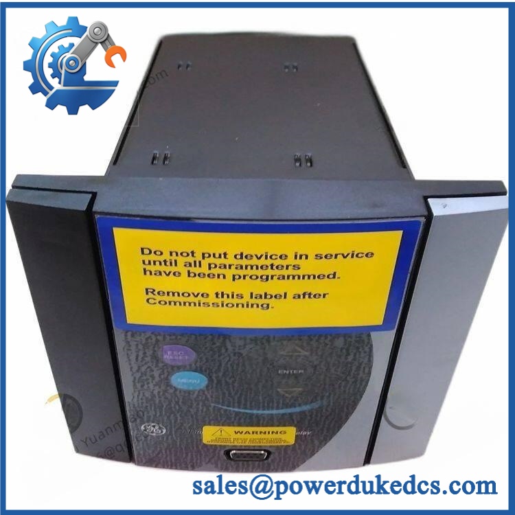
GE MIFIIPI55E00HI00
Module 4: Compatibility & Installation Traps
Migration/Compatibility
- Replacement type: GE Multilin MIF II digital feeder protection relay
- Complete ordering code: MIFII-P-I-5-5-E-0-0-HI-0-0
- System family: MIF II feeder protection
- Phase configuration: Three-phase plus ground
- Phase CT input: 5 A
- Ground CT input: 5 A
- Power supply: 110–250 VDC nominal high-range configuration
- Protection curve: IEC
- Recloser: Not included in this configuration
- Communications: Standard Modbus RTU
- Conformal coating: Not included
- Firmware flash: May be required, depending on firmware revision and the existing relay configuration
- Logic rewrite: Normally not required for an identical relay replacement, but all settings and logic should be restored and verified
- Drop-in status: Potentially direct only when the complete ordering code and CT/power configuration match the installed relay
GE states that the MIF II supports adjustable overcurrent protection, configurable I/O on option-equipped models, front RS-232 and rear RS-485 communications, and EnerVista-based configuration. The manufacturer now lists MIF II as a legacy product, so exact-match sourcing is particularly important for existing installations.
⚠️ Field Traps (Watch Out)
1. Never connect a 5 A CT relay to an incompatible CT secondary arrangement.
The exact code specifies 5 A phase and 5 A ground CT inputs. Confirm the CT ratios, polarity, grounding arrangement, and secondary wiring before energizing the relay. CT secondaries must never be opened while energized.
2. The HI power option is not the LO version.
The HI code specifies the 110–250 VDC family, with a documented allowable range of 88–300 VDC. Do not install a low-range 24–48 VDC version simply because the enclosure and front panel look identical.
3. Confirm the exact protection curve before restoring settings.
This unit uses IEC curves. Replacing it with a relay configured for ANSI, IAC, or another curve can materially change trip timing and coordination even when the pickup current appears correct.
4. Basic model means no optional recloser function.
The ordering code ends with the basic option structure and 0 for recloser. Do not assume a replacement relay with a different suffix has identical breaker-control functionality.
5. Conformal coating is not specified.
The final 00 configuration indicates no harsh-environment conformal coating. A coated version should not be substituted without confirming enclosure environmental requirements and the complete ordering code.
Module 5: Quality Assurance SOP
Each GE MIFIIPI55E00HI00 unit should pass a documented pre-shipment inspection sequence:
- OEM anti-counterfeit visual inspection: Verify GE Multilin identification, complete MIFIIPI55E00HI00 ordering code, serial number, front-panel markings, terminals, display, keypad, and enclosure construction.
- Exact order-code verification: Decode and document the complete configuration: P-I-5-5-E-0-0-HI-0-0.
- Hardware inspection: Check CT/PT terminals, auxiliary supply terminals, communication ports, relay output terminals, display, keypad, terminal covers, and mounting hardware for damage or contamination.
- Power-input inspection: Verify the high-range supply configuration and inspect the supply terminals for overheating, loose hardware, or electrical damage.
- Power-on self-test (POST): Energize the relay using a controlled 110–250 VDC test supply and verify successful initialization, display operation, keypad response, diagnostic status, and absence of persistent hardware alarms.
- CT-input verification: Apply calibrated secondary-current injection to the 5 A phase and ground inputs and verify pickup and metering accuracy against the approved test limits.
- Protection-function testing: Verify representative phase and ground overcurrent elements, including time-overcurrent and instantaneous functions, using calibrated secondary injection.
- Output-relay verification: Test all applicable electromechanical Form C outputs and confirm correct contact transitions under controlled conditions. The MIF II documentation specifies six output relays.
- Communication handshake verification: Test the front RS-232 service interface and rear RS-485 Modbus RTU connection where the test environment supports them.
- Configuration verification: Load or compare the approved application settings, CT ratios, protection pickups, time curves, logic, output assignments, and communications address/baud parameters.
- Event and metering check: Where the configuration supports these functions, verify metering, event records, and fault-reporting behavior.
- Final QC: Record serial number, hardware/firmware revision, secondary-injection results, communication results, and restored configuration; photograph the nameplate and package the relay securely.
Module 6: CRO-Driven Buyer FAQ
1. What is GE MIFIIPI55E00HI00?
It is a GE Multilin MIF II Digital Feeder Protection Relay configured as a three-phase plus ground, 5 A phase/ground CT, IEC-curve, high-range power-supply model. GE describes MIF II as a feeder protection relay for distribution networks, with auxiliary applications for transformers, generators, and motors.
2. What does the full MIFII-P-I-5-5-E-0-0-HI-0-0 code specify?
It specifies three-phase plus ground operation, 5 A phase CT, 5 A ground CT, English language, basic option configuration, no recloser, 110–250 VDC high-range power, standard Modbus RTU, and no harsh-environment conformal coating.
3. Can the MIFIIPI55E00HI00 be hot-swapped?
Do not assume hot-swap capability. The relay is connected to energized CT circuits and trip/control wiring, so replacement should follow the approved protection-system maintenance procedure. CT secondary circuits require particular attention and must not be left open while energized.
4. Does replacement require a new protection logic program?
A same-configuration replacement normally does not require redevelopment of the protection scheme. The relay settings, CT ratios, IEC curves, pickup levels, time delays, output assignments, communications parameters, and any enabled logic must be restored and independently validated before the feeder is returned to service.
5. Is the MIF II still manufactured?
GE currently classifies MIF II as a legacy product. That increases the value of exact-match spare inventory, particularly where the existing panel wiring, protection settings, and SCADA interface were designed around the original relay. GE identifies the 350 relay as an alternative product family for MIF applications, but migration should be engineered rather than treated as a blind replacement.











 Start Chat


