

Description
- Brand: GE Multilin
- Full Model Number: MIFIIPI55E10HI00
- Product Type: Microprocessor Feeder Protection Relay
- System/Series Family: GE MIFII
- Core Function: Protection and control of electrical feeders using configurable microprocessor-based protection functions
- Top 3 Hardcore Specs: MIFII platform | 5 A CT input class | HI control-power configuration
- Protection Class: Feeder protection and control
- Technology: Microprocessor-based relay
- Firmware References: MIFII versions including 3.03 and 4.01 are associated with this exact ordering code in relay-model databases.
- Stock Status: New surplus / condition to be confirmed per available unit
Module 3: Technical Product Introduction
A feeder relay has to make a protection decision quickly enough to isolate a fault while avoiding unnecessary trips during normal system disturbances. GE MIFIIPI55E10HI00 belongs to the GE MIFII family of microprocessor-based feeder protection relays. Independent relay-model documentation identifies this exact ordering code under the MIFII 3.03 and 4.01 versions and classifies the MIFII as a microprocessor feeder protection/control relay.
The P55 configuration and HI00 suffix are part of the relay’s hardware ordering code, so the complete model should be retained when sourcing a replacement. Exact CT/VT ranges, auxiliary supply, I/O arrangement, and enabled protection functions should be verified against the relay nameplate and configuration records rather than inferred from the model string. —This matters particularly on legacy protection equipment, where two MIFII variants can look similar while carrying different electrical options.
Module 4: Application Scenarios & Field Realities
- On industrial distribution feeders, the MIFII provides the protection and control layer between current/voltage transformers and the feeder switching equipment. CT and VT wiring should be verified before any replacement relay is energized.
- For substations with multiple outgoing feeders, protection coordination is the main commissioning concern. Pickup values, time delays, directional elements, and breaker logic need to remain consistent with the site’s approved coordination study.
- During a feeder trip investigation, examine the relay event records and measured quantities before resetting the protection. A replacement should not be commissioned simply because it clears the alarm; the original trip cause still needs to be established.
- When maintaining older MIFII installations, record the firmware version as well as the complete ordering code. The exact MIFIIPI55E10HI00 model is documented against multiple MIFII firmware versions, so firmware compatibility should be checked before transferring or restoring settings.
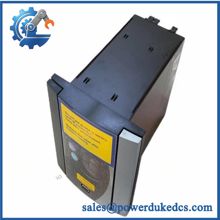
GE MIFIIPI55E10HI00
Module 5: Migration, Compatibility & Installation Traps
Replacement Matrix
| Replacement Type | MIFIIPI55E10HI00 Assessment |
|---|---|
| Drop-in Replacement | Yes, when replacing the same MIFIIPI55E10HI00 configuration in a compatible GE MIFII installation |
| Software Compatible | Configuration-dependent; firmware, protection settings, logic, and communications parameters must be verified |
| Hardware Modification Required | Not expected for an exact replacement; required if CT/VT, auxiliary power, I/O, or terminal configuration differs |
Field Traps — Watch Out
1. Confirm the firmware before transferring settings.
This exact model is associated with multiple MIFII firmware versions in published relay databases. Verify the existing firmware and confirm that the replacement can accept the site’s saved configuration.
2. CT circuits require controlled isolation.
Before disconnecting current-transformer wiring, follow the site’s approved CT shorting and isolation procedure. Never open an energized CT secondary circuit casually.
3. Preserve the protection coordination settings.
Record phase overcurrent, ground-fault, directional, voltage, frequency, breaker-failure, and other enabled elements before replacing the relay. Not every MIFII installation uses the same protection scheme.
4. Verify the complete terminal configuration.
Do not assume that another MIFII relay with a similar front panel has identical CT/VT, auxiliary input, trip-output, or communication terminals.
Module 6: Quality Assurance SOP
Before shipment, each available GE MIFIIPI55E10HI00 should pass a documented protection-relay inspection sequence:
- OEM identification inspection — Verify GE/GE Multilin markings, complete ordering code, serial information, hardware revision, and nameplate data.
- OEM anti-counterfeit visual inspection — Examine the enclosure, front display/keypad, PCB workmanship, connectors, terminal blocks, labels, and component markings for unauthorized modification.
- Physical inspection — Check the housing, display, keypad, terminal screws, connector interfaces, mounting points, and PCB surfaces for corrosion, cracking, contamination, or mechanical damage.
- Part-number verification — Confirm the physical relay against the exact requirement before electrical testing.
- Controlled power-on test — Apply the specified auxiliary supply under protected laboratory conditions and verify normal initialization and self-diagnostic status.
- Display/keypad verification — Test representative menu navigation, display segments, operator keys, and relay status indications.
- Metering verification — Apply controlled simulated CT/VT inputs within the applicable test limits and verify measured quantities against known references.
- Protection-function simulation — Use an appropriate relay test set to simulate representative feeder fault conditions and verify pickup and timing behavior for the configured protection elements.
- Trip-output verification — Confirm applicable breaker-trip and auxiliary output contacts operate correctly during controlled protection tests.
- Communication handshake verification — Connect the relay to the applicable test environment and verify the configured communications interface, addressing, data exchange, and relay measurements.
- Event and diagnostic verification — Generate controlled test events and confirm that the relay records the expected protection and diagnostic information.
- Extended stability test — Operate the relay under controlled conditions and monitor for resets, display abnormalities, unexpected trips, communication interruptions, or thermal issues.
- Final visual inspection — Recheck terminals, connectors, labels, housing, and mounting hardware after testing.
- Test record and packaging — Record the model number, firmware version where available, test results, inspection date, and packaging condition before dispatch.
QA note: A protection relay should not be accepted merely because its display starts normally. For the , controlled CT/VT simulation, protection-element testing, trip-contact verification, event-record checks, and communications testing provide substantially stronger evidence of operational condition.











 Start Chat


