

Description
- Brand: GE Multilin
- Full Model Number: MIVII1000E00HI00
- Lifecycle Status: Obsolete / Legacy
- Core Function: Digital voltage protection relay
- Top 3 Technical Specs: 10–250 V voltage setting range | 110–250 VDC / 110–230 VAC high-range power supply | Modbus RTU via RS232/RS485
- Form Factor: 1/4 of a 19-inch rack drawout case
- Local Interface: 5-button keypad | 16 × 2 LCD
- Protection Functions: Phase undervoltage 27P | Phase overvoltage 59P | Ground overvoltage 59G | Phase reversal 47
- Stock & Condition: Stock confirmation required | New Surplus / Tested Refurbished subject to quotation
- Shipping: Emergency dispatch subject to stock, QA completion, and carrier cutoff
The GE MIV II documentation identifies the MIV II 1000 as the voltage-function version, with a 10–250 V voltage range. The complete order-code format also identifies E as English and HI as the 110–250 VDC / 110–230 VAC power-supply option; the final 00 denotes no conformal-coating option.
Obsolescence & Supply Chain Deep Dive
When an installed MIV II 1000 fails, the technical problem is usually straightforward; obtaining the exact legacy configuration is not. GE’s own retrofit documentation describes the MII relay family as aging and presents the Multilin 3 Series as an updated retrofit path. That makes the MIVII1000E00HI00 particularly relevant as a maintenance spare when the existing panel, wiring, settings, and protection philosophy are still being retained. The exact order code matters because the MIV II family uses different voltage ranges and auxiliary-power configurations.
For TCO analysis, an exact replacement can keep an otherwise serviceable protection circuit operating without immediately funding a full relay migration. The MIV II provides voltage metering, local configuration through its keypad and LCD, and computer access through serial communication using Modbus RTU. GE documentation also specifies its 1/4-rack drawout construction. Reusing the installed hardware can therefore avoid panel alterations and broader commissioning work—though a plant should still budget for protection-setting verification and functional testing after replacement.
Compatibility & Replacement Matrix
| Replacement Path | Compatibility Position | Required Engineering Action | Indicative Switch Time | Indicative Cost |
|---|---|---|---|---|
| MIVII1000E00HI00 → MIVII1000E00HI00 | Drop-in Replacement | Verify complete order code, power supply, voltage range, wiring, settings, and physical fit | 1–3 technician hours | Labor-only estimate: US150–450 |
| MIV II 1000 → Same-family MIV II with different option code | Software/Hardware compatibility requires verification | Confirm voltage range, auxiliary supply, language/options, terminal assignment, and settings | 2–6 engineering hours | Typically higher due to validation and reconfiguration |
| MIV II 1000 → Multilin 3 Series retrofit | Hardware Modification Required | Follow retrofit wiring and mounting requirements; convert settings and validate protection functions | 1–3 engineering days | Project-specific; hardware and commissioning separate |
The replacement guide explicitly documents conversion from MIV II relays to the Multilin 3 Series and includes a dedicated MIV II wiring section plus a MIV II-to-350 retrofit wiring section. This means a newer relay should not be treated as a plug-in substitute simply because its protection functions appear similar.
Field Traps to Watch Out For
Auxiliary power mismatch: The HI configuration accepts 110–250 VDC with an 88–300 VDC operating range or 110–230 VAC with an 88–264 VAC operating range. A replacement carrying a different power-supply code should be held for engineering review.
Voltage-range mismatch: MIV II 1000 supports the 10–250 V range, while the MIV II 1000 ordering structure also distinguishes a low-voltage option of 2–60 V. Confirm the existing relay’s full order code before approving an apparently similar unit.
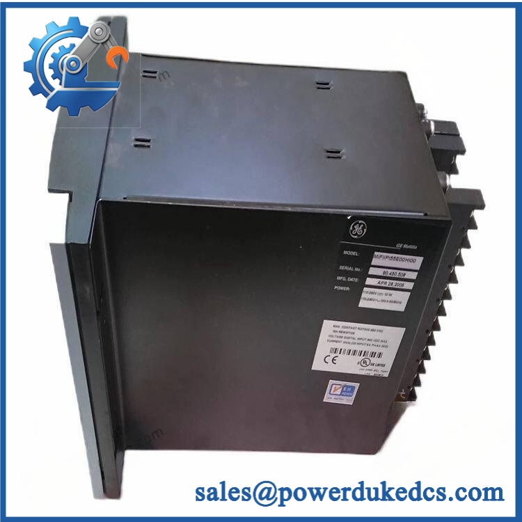
GE MIVII1000E00HI00
Quality Assurance & Testing SOP
Identity and authenticity inspection
- Record the exact MIVII1000E00HI00 order code before testing.
- Photograph the front faceplate, manufacturer markings, serial information, terminals, connectors, and rear label.
- Conduct an OEM anti-counterfeit visual inspection for altered labels, inconsistent typography, abnormal fasteners, reworked soldering, contamination, corrosion, and unauthorized PCB modification.
- Compare the received configuration against the customer-approved reference.
Mechanical inspection
- Check drawout mechanism, enclosure, terminal blocks, connector pins, keypad, LCD, and mounting hardware.
- Inspect the 5-button keypad for sticking or intermittent operation.
- Confirm the LCD initializes without abnormal characters or missing display segments.
Power-on verifications
- Apply the appropriate controlled auxiliary supply for the HI configuration.
- Perform a power-on self-test (POST) and record startup behavior.
- Check the installed status LEDs for expected operating indications and document any ERR or abnormal alarm state.
- Confirm measured auxiliary voltage remains within the applicable operating range.
Protection-function testing
- Inject controlled voltage conditions through an approved relay test system.
- Verify representative undervoltage, overvoltage, ground-voltage, and phase-reversal functions against the programmed settings.
- Confirm phase and ground voltage metering responds correctly.
- Test relay outputs and applicable digital inputs under controlled conditions.
Communication testing
- Establish communication through the supported serial interface.
- Verify Modbus RTU communications, relay addressing, baud-rate configuration, and stable data exchange.
- Confirm settings can be read back without communication errors. GE documentation identifies front RS232 and rear RS485 communication interfaces for computer access.
Final release
- Record test results against the unit’s serial number or internal inventory identifier.
- Capture final photographs after testing.
- Package the relay in ESD-protective material with mechanical protection around the drawout assembly.
- Release only after the inspection, functional test, and documentation checks are complete.
Procurement & Lifecycle FAQ
Is the GE MIVII1000E00HI00 genuinely in stock and what is the emergency shipping cutoff?
Actual warehouse quantity should be confirmed before the PO is released. For an urgent outage, request confirmation of the exact order code, physical stock location, QA status, packed weight, and same-day carrier cutoff. A quoted availability date should not be treated as a physical stock guarantee until the specific unit has been allocated.
How do you verify the condition and authenticity of an obsolete MIVII1000E00HI00?
The inspection should start with the complete order code rather than the front-panel appearance alone. Verify , manufacturer markings, serial information, PCB condition, connectors, enclosure, keypad, LCD, and auxiliary-power configuration, followed by controlled electrical and protection-function testing.
Are there firmware or configuration issues my engineers should check before issuing the PO?
The more immediate compatibility risks are the order-code options, voltage range, auxiliary power configuration, wiring, relay address, baud rate, and existing protection settings. The GE retrofit documentation also indicates that MIV II settings can be handled as part of migration to the 3 Series, so a modernization project should include settings conversion and verification rather than assuming the legacy settings can simply be copied unchanged.
Is the a direct replacement for an existing MIV II 1000?
When the existing installation uses the same MIV II 1000 configuration and HI auxiliary-power option, an exact-order-code replacement is the appropriate direct-replacement route. Confirm the complete nameplate code and terminal wiring before installation. A different MIV II option or a newer Multilin relay should undergo an engineering compatibility review.
What warranty and return terms should procurement specify?
The commercial quotation should state the warranty period for the actual supplied condition, the return-authorization procedure, failure-reporting window, inspection requirements, and exclusions for incorrect installation, wiring errors, unauthorized modification, and site-related electrical damage. For an obsolete protection relay, retaining pre-shipment test records and photographs is especially useful for warranty traceability.











 Start Chat


