

Description
- Brand: GE Multilin
- Full Model Number: MMII-PD-1-2-120
- System/Series Family: MM2 Motor Manager
- Core Function: Motor protection, control, monitoring, and process control
- Top 3 Hardcore Specs: 120 VAC control power | Panel mount with display | Options 1 + 2 installed
- Option 1: Process control, 10 process inputs, undervoltage autorestart, diagnostics
- Option 2: Enhanced protection, power measurement, thermistor, second contactor control, 2 process inputs
- Communications: RS485 serial interface; 1,200–19,200 bps reported
- Display: Panel-mounted local display
- Stock Status: New surplus, factory sealed, or fully tested refurbished subject to exact inventory confirmation
The GE Multilin MMII-PD-1-2-120 is an MM2 Motor Manager configured for panel mounting with a display, both Option 1 and Option 2, and 120 VAC control power. The ordering structure is significant: PD identifies the panel-mount/display configuration, while 1 and 2 identify the two optional feature groups.
Module 3: Technical Product Introduction
A motor protection replacement becomes complicated when the original relay combines protection, control, process inputs, and contactor functions in one package. The GE Multilin MMII-PD-1-2-120 is designed for that type of motor-management architecture. It combines motor protection and control functions with a local panel display, while Option 1 adds process-control functions, undervoltage autorestart, and diagnostics. Option 2 adds enhanced protection, power measurement, thermistor functionality, second-contactor control, and additional process inputs.
The 120 VAC control-power rating must be matched exactly during replacement. Available technical records specify an operating temperature range of 0°C to 60°C, 4-20 mA analog input capability, and RS485 communication with baud rates from 1,200 to 19,200 bps. The reported physical size is approximately 7.4 × 5 × 4.4 inches, with a weight around 3 lb / 1.36 kg.
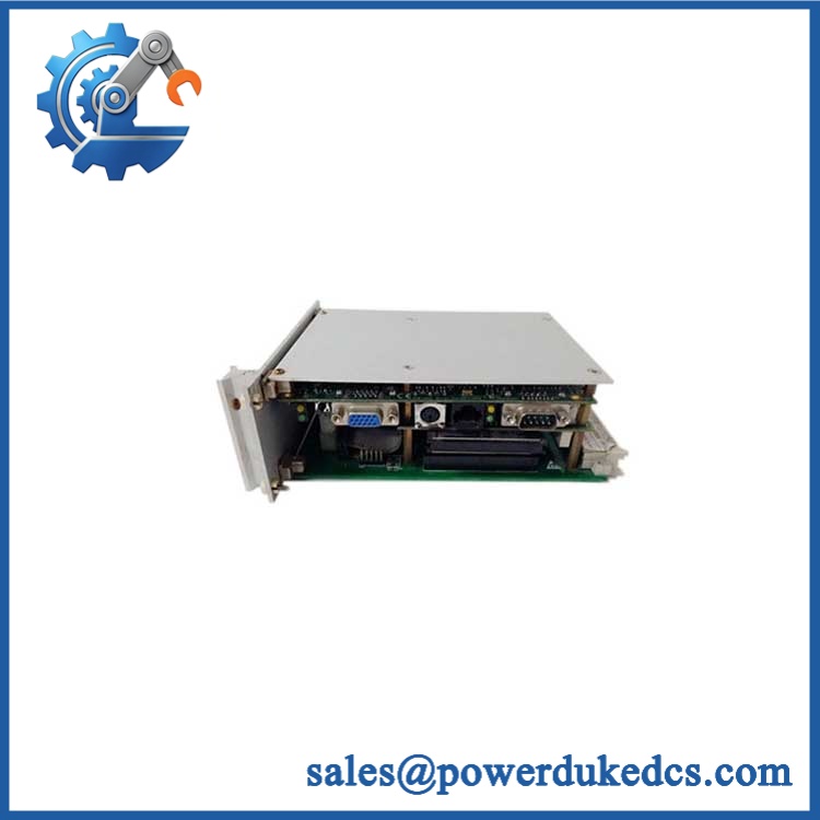
GE Multilin MMII-PD-1-2-120
Module 4: Application Scenarios & Field Realities
- Inside motor control centers, the MMII can consolidate protection and control functions that would otherwise require several discrete devices. When replacing one, document the contactor-control wiring and process inputs before disconnecting the original unit.
- For pumps and process motors, Option 1 provides process-control functions and undervoltage autorestart capability. The restart logic deserves particular attention: the replacement should retain the intended delay and operating conditions rather than simply enabling autorestart because the feature is available.
- On motors requiring enhanced protection, Option 2 adds functions including ground-fault, stalled-rotor, undercurrent/underpower, and voltage-related protection. The exact active protection functions should be verified against the original configuration and motor protection study.
- Where plant control systems collect motor data remotely, the RS485 interface can be integrated into a serial communications network. Verify the original baud rate, addressing, wiring polarity, and communication parameters before commissioning. A working display does not prove that the remote communications path is correctly configured.
Module 5: Migration, Compatibility & Installation Traps
Replacement Matrix
| Replacement Type | Assessment | Engineering Requirement |
|---|---|---|
| Drop-in Replacement | Potentially yes for an identical MMII-PD-1-2-120 configuration | Match PD mounting, Options 1 + 2, 120 VAC control power, terminals, and hardware revision |
| Software Compatible | Configuration-dependent | Restore motor settings, protection thresholds, process-control settings, autorestart parameters, and communications |
| Hardware Modification Required | Potentially required for a different MMII configuration | Verify mounting, control wiring, process inputs, contactor outputs, and auxiliary connections |
Field Traps — Watch Out
1. The option digits are critical: In MMII-PD-1-2-120, the first 1 represents the process-control option and the second 2 represents enhanced protection. The PD display configuration is specifically associated with having both options selected.
2. 120 VAC control power: Do not assume that another MMII with the same enclosure or display is electrically equivalent. The final 120 identifies the 120 VAC control-voltage configuration. Other MMII variants are available with different control voltages.
3. Autorestart can create a process hazard: Option 1 includes undervoltage autorestart. Before restoring the function, verify the existing motor-control sequence, restart delay, permissives, and plant safety logic. A replacement should not introduce an automatic restart behavior that was not intended by the operating scheme.
4. Process-input wiring: The MMII uses process inputs in addition to conventional motor-protection signals. Photograph and label every terminal before removal. A misplaced process signal can produce an apparently healthy controller with incorrect process decisions.
5. Communication parameters: RS485 communication depends on the correct serial settings and network wiring. Confirm baud rate, address, parity, and termination requirements against the existing installation before reconnecting the unit. Available specifications report 1,200–19,200 bps communication rates.
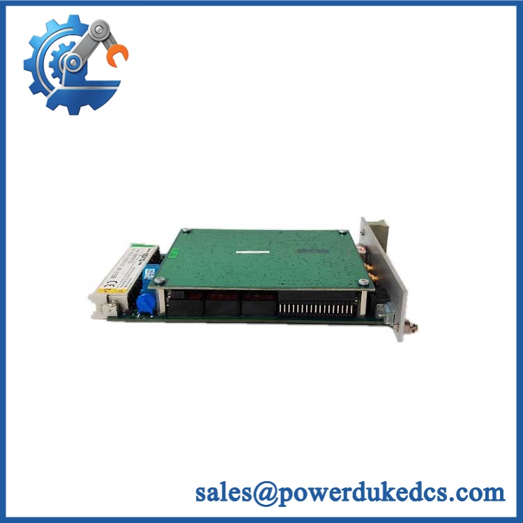
GE Multilin MMII-PD-1-2-120
Module 6: Quality Assurance SOP
Before shipment, each GE Multilin MMII-PD-1-2-120 should undergo a documented inspection sequence appropriate to the available MM2 test equipment.
- Step 1 — Part-number verification: Record MMII-PD-1-2-120, serial number, hardware revision, firmware information where available, and all visible GE Multilin identification.
- Step 2 — OEM anti-counterfeit visual inspection: Inspect the GE Multilin label, front-panel display, keypad, status indicators, terminal blocks, connectors, enclosure, and manufacturing markings. Photograph the complete nameplate.
- Step 3 — Physical condition inspection: Check the enclosure, display window, keypad, mounting hardware, terminal screws, connectors, and PCB for corrosion, contamination, cracked components, loose hardware, or evidence of previous repair.
- Step 4 — Control-power verification: Confirm the test fixture supplies 120 VAC before energizing the unit. Measure the applied voltage directly at the test connection and record the result.
- Step 5 — Power-on self-test (POST): Energize the MMII under controlled conditions and verify display initialization, keypad response, status indicators, diagnostic messages, and startup behavior.
- Step 6 — Motor-input verification: Apply suitable calibrated test signals to representative motor-protection inputs and verify correct measurement and scaling.
- Step 7 — Process-input verification: Exercise representative process inputs associated with Option 1 and Option 2. Confirm that the controller detects the expected input states and values.
- Step 8 — Protection-function verification: Using an appropriate relay test setup, verify representative protection functions supported by the installed configuration, including overload, phase-related protection, ground fault, stalled rotor, undercurrent/underpower, and voltage protection where applicable.
- Step 9 — Contactor and relay output verification: Exercise the applicable contactor-control and auxiliary relay outputs. Confirm contact state and terminal assignment against the test record.
- Step 10 — Communication handshake verification: Connect the RS485 interface to suitable test equipment and verify communication at an appropriate baud rate. Confirm that representative motor status and measurement data can be read.
- Step 11 — Display and operator-interface verification: Confirm display readability, keypad operation, status LEDs, and access to representative configuration and diagnostic screens.
- Step 12 — Final photographic record: Photograph the complete MMII, model label, serial number, display, terminal area, connectors, and final packaging.
QA release criterion: A successful power-up establishes only basic controller operation. A fully tested MMII-PD-1-2-120 should have documented control-power, input, protection, output, display, and communication checks. Final commissioning must also verify motor-specific settings, CT/input configuration, contactor logic, autorestart behavior, process interlocks, and coordination with the plant protection system.











 Start Chat


