

Description
Module 2: The 10-Second Buyer’s Brief
- Brand: GE Multilin
- Full Model Number: PQMII-T20-C-A
- System/Series Family: GE Multilin PQM II Power Quality Meter
- Core Function: Electrical power monitoring, protection, control, and power-quality analysis
- Top 3 Hardcore Specs: 90–300 VDC / 70–265 VAC control power; 4 isolated 0–20/4–20 mA analog outputs; RS485 and Modbus communications
- Stock Status: New Surplus — exact hardware revision, firmware, and modification number to be confirmed before shipment
GE’s current documentation confirms the PQMII-T20-C-A ordering code and identifies the T20 option as four isolated analog outputs, a 4–20 mA analog input, and a second RS485 port. The C option adds three programmable output relays and four programmable switch inputs, while A adds harmonic analysis, waveform capture, event recording, data logging, and voltage disturbance recording.
Module 3: Technical Product Introduction
When a plant loses its power-quality meter, the immediate problem is not simply loss of a display. Operators may lose visibility of voltage, current, power, demand, harmonics, alarms, and recorded disturbances at the same time. The GE Multilin PQMII-T20-C-A combines electrical metering with control and power-analysis functions in a panel-mounted PQM II platform. Its standard control-power range is 70–265 VAC or 90–300 VDC, while the T20 configuration provides four isolated analog outputs, a 4–20 mA analog input, and a second RS485 port.
The option code is where the real specification resides. T20 provides four isolated 0–20/4–20 mA outputs plus the additional RS485 interface; C provides three additional programmable output relays, bringing the total to four, together with four programmable switch inputs; A adds harmonic analysis, triggered waveform capture, event recording, data logging, and voltage disturbance recording. The PQM II documentation also records a 25 MHz CPU platform on newer hardware revisions, with the Voltage Disturbance Recorder requiring that platform.
Module 4: Application Scenarios & Field Realities
- At a main switchgear lineup, the PQMII can consolidate voltage, current, power, demand, and alarm information instead of requiring separate instruments for each measurement. The T20 analog outputs can also pass selected measurements to a PLC or DCS through 4–20 mA signals.
- Where variable-frequency drives and electronic loads are producing distortion, the A power-analysis option becomes particularly useful. Harmonic analysis can help identify conditions associated with transformer, motor, capacitor, or neutral-conductor heating.
- During an unexplained feeder disturbance, waveform capture and event records provide information that a simple instantaneous meter reading cannot. The A option includes triggered waveform capture and a voltage disturbance recorder for this purpose.
- For PLC/DCS integration, the RS485 interface and Modbus protocol allow monitored values to be transferred digitally. The PQM II documentation also provides a separate communications guide and Modbus memory-map documentation, which should be used when rebuilding an existing integration.
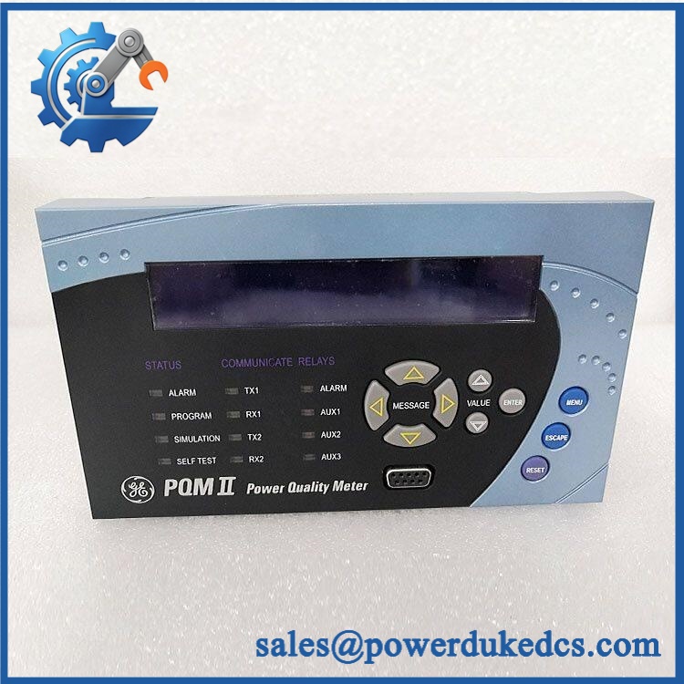
GE PQMII-T20-C-A
Module 5: Migration, Compatibility & Installation Traps
Replacement Matrix
| Replacement Type | PQMII-T20-C-A Assessment | Engineering Requirement |
|---|---|---|
| Drop-in Replacement | Yes, for a matching PQM II installation | Match complete option code, control-power range, terminal arrangement, and hardware revision |
| Software Compatible | Yes, configuration-dependent | Restore setpoints, CT/PT parameters, communication settings, and alarm configuration |
| Hardware Modification Required | Potentially | Required when changing from different analog, control, power, or communications options |
Field Trap 1 — Do not treat “PQM II” as the complete model:
GE explicitly states that T20, C, and A appear in the model number only when those respective options are installed. Therefore, a basic PQM II is not equivalent to PQMII-T20-C-A.
Field Trap 2 — CPU revision affects power-analysis functions:
The PQM II documentation states that newer hardware revisions use a 25 MHz CPU, while older revisions use 16 MHz. Certain functions, including the Voltage Disturbance Recorder, require the 25 MHz platform. Verify the actual hardware revision before assuming every PQM II can reproduce the configuration of a T20-C-A unit.
Installation note: Record the original CT/PT ratios, system voltage configuration, frequency, alarm thresholds, analog-output assignments, relay logic, RS485 address, baud rate, parity, and Modbus settings before removing the existing meter. The meter’s electrical measurement accuracy depends heavily on correct transformer and system configuration.
Module 6: Quality Assurance SOP
- OEM identification inspection — Verify the GE Multilin PQMII-T20-C-A model designation, serial number, version, date information, and complete product label.
- Option-code verification — Confirm that the actual hardware corresponds to T20 + C + A, rather than a base PQM II or a unit with only one or two of these options. GE’s manual uses the complete order code as the product configuration identifier.
- Physical inspection — Examine the display, keypad, enclosure, terminal blocks, connectors, mounting hardware, and accessible PCB areas for corrosion, contamination, impact damage, loose components, or evidence of modification.
- OEM anti-counterfeit visual inspection — Compare GE Multilin labeling, enclosure construction, terminal layout, display/keypad arrangement, and internal identification markings against known PQM II hardware.
- Power-on self-test (POST) — Apply the correct control voltage within the 70–265 VAC / 90–300 VDC range under controlled laboratory conditions and verify startup, display operation, keypad response, and diagnostic status.
- Analog I/O verification — Test the four T20 isolated analog outputs across their configured 0–20 mA or 4–20 mA range and verify the 4–20 mA analog input using an appropriate calibrated current source.
- Relay and switch-input verification — Exercise the four programmable switch inputs and verify the four programmable output relays associated with the C option.
- Communication handshake verification — Establish RS485 communication using the applicable Modbus configuration and verify that representative measurement registers can be read correctly. GE provides dedicated PQM II communications and Modbus documentation for this interface.
- Power-analysis verification — Where the test facility supports it, verify harmonic measurement, event recording, waveform capture, data logging, and voltage-disturbance functions associated with the A option.
- Firmware and CPU verification — Record the main program version, boot version, CPU platform, and modification number. The PQM II itself exposes these values through its Product Information menus.
- Final traceability record — Photograph the complete model label, document serial/revision information, record test results, and package the meter with suitable ESD and mechanical protection.
For PQMII-T20-C-A, the complete order code should be preserved in the procurement record. GE’s documentation confirms that the three option groups materially change the meter’s hardware and analytical functions, while hardware revision and CPU speed can affect available power-analysis features.











 Start Chat


