

Description
- Brand: GE / GE Multilin
- Full Model Number: SR489-P5-HI-A20-E
- System/Series Family: GE Multilin 489 Generator Management Relay
- Core Function: Generator protection, control, monitoring, metering, and event recording
- Phase CT Inputs: 5 A secondary
- Control Power: 90–300 VDC / 70–265 VAC, 48–62 Hz
- Analog Outputs: 4–20 mA
- Display: Enhanced LCD display
- Communications: RS-232, 2 × isolated RS-485, 10 Mbps Ethernet
- Protocols: Modbus RTU, Modbus TCP/IP, DNP 3.0 Level 2
- RTD Inputs: 12 configurable RTD channels
- Fault Recording: Up to 20 oscillography records
- Event Recording: Up to 479 events with 1 ms time resolution
- Environmental Range: -40°C to +60°C operating
- Mounting: Drawout relay case
- Stock Status: New Surplus / Fully Tested Refurbished — verify exact hardware revision, firmware, and case configuration
GE’s current 489 documentation identifies the P5 ordering option for 5 A phase CT inputs, HI for the high-range control supply, and A20 for 4–20 mA analog outputs. The E configuration provides the enhanced display.
Module 3: Commercial-Technical Deep Dive
Generator protection requires more than a collection of independent trip elements. The GE Multilin SR489-P5-HI-A20-E combines generator protection, control, metering, monitoring, event recording, and communications in one relay. The P5 option specifies 5 A phase CT secondaries, while the HI power-supply configuration accepts 90–300 VDC or 70–265 VAC at 48–62 Hz. A20 provides 4–20 mA analog outputs, and the E suffix identifies the enhanced display configuration with a larger LCD and improved keypad.
The operational value is concentrated protection and diagnostic data at the generator switchgear. GE specifies two isolated RS-485 ports, a front RS-232 port, and 10 Mbps copper Ethernet, with Modbus RTU, Modbus TCP/IP, and DNP 3.0 Level 2 communications available on the platform. The relay can record up to 20 oscillography records at 64 samples per cycle and up to 479 sequence-of-events records with 1 ms timestamp resolution. —Do not assume every protection option or communication function is enabled identically on every 489; the installed ordering code and firmware must be checked before commissioning.
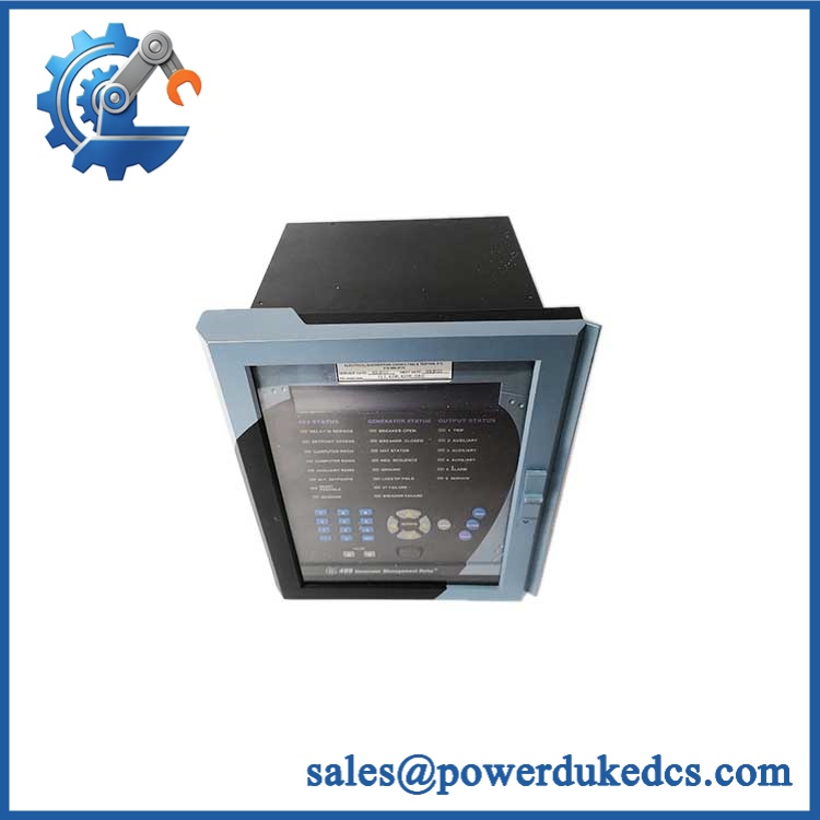
GE SR489-P5-HI-A20-E
Module 4: Compatibility & Installation Traps
Migration/Compatibility
For an existing protection panel specified for SR489-P5-HI-A20-E, the correct strategy is a like-for-like 489 relay replacement, with the complete ordering code, hardware revision, firmware, and drawout case verified before installation.
A protection-setting rewrite should not be assumed, but configuration restoration is essential. The replacement relay should receive the approved generator settings, CT/VT configuration, programmable logic, communications parameters, and alarm/trip assignments. The GE 489 platform is configured through its dedicated setup software, so preserve the original settings file wherever the failed relay remains accessible.
⚠️ Field Traps (Watch Out)
- P5 is a 5 A CT input configuration: Do not connect a 1 A CT secondary system to this relay simply because the front-panel model says “489.” GE specifies P1 for 1 A and P5 for 5 A phase CT secondaries.
- HI supply range: The HI version accepts 90–300 VDC or 70–265 VAC, while LO versions use a substantially lower supply range. Verify the nameplate before energization.
- Analog-output mismatch: A20 means 4–20 mA outputs; A1 is a separate 0–1 mA configuration. The downstream SCADA/DCS scaling must match the actual relay hardware.
- CT wiring safety: Never open-circuit a live CT secondary. Apply the protection-panel CT shorting and isolation procedure before disconnecting the relay.
- Drawout case matching: The 489 relay and its case have identification labels that document permitted combinations. Verify the replacement relay against the installed case before energizing.
Module 5: Quality Assurance SOP
- OEM anti-counterfeit visual inspection — verify GE Multilin markings, complete SR489-P5-HI-A20-E ordering code, serial number, display, keypad, terminal configuration, and evidence of unauthorized modification.
- Part-number reconciliation — photograph the relay nameplate and record phase-CT rating, control-power range, firmware revision, and manufacture information.
- Case compatibility inspection — verify the relay is matched to the intended SR489 drawout case and that the case identification permits the unit.
- Power-on self-test (POST) — apply the correct high-range control supply and verify startup, LCD operation, keypad response, status LEDs, and diagnostic messages.
- CT input verification — inject calibrated 5 A-secondary test currents and verify phase-current measurement accuracy and phase identification.
- Voltage and metering verification — apply representative secondary voltage signals and verify calculated voltage, power, frequency, and related metering values.
- Protection-element verification — test representative overcurrent, under/overvoltage, frequency, thermal, loss-of-excitation, reverse-power, and other functions required by the customer’s approved settings.
- RTD verification — simulate representative RTD resistance values and confirm alarm/trip behavior for the configured channels.
- Trip/relay-output verification — verify each required output contact under controlled test conditions, including trip, alarm, breaker-failure, and supervision functions where configured.
- 4–20 mA verification — validate analog-output scaling at representative points such as 4 mA, 12 mA, and 20 mA.
- Communication handshake verification — test RS-485 and Ethernet communications using the customer’s applicable Modbus or DNP configuration. GE specifies RS-485 baud rates from 300 to 19,200 baud.
- Oscillography and event-recording test — generate controlled protection events and verify event capture and timestamp behavior.
- Stability observation — operate the relay under representative metering, protection, and communication load while monitoring for resets, abnormal alarms, or communication dropouts.
- Final QC release — retain nameplate photographs, firmware information, injection-test results, communication logs, and final configuration records.
For a generator protection relay, a successful display startup is only the first checkpoint. The meaningful acceptance test covers current measurement, protection operation, trip outputs, communications, and the approved generator settings.
Module 6: CRO-Driven Buyer FAQ
1. What does SR489-P5-HI-A20-E mean?
The ordering code identifies several hardware options: P5 = 5 A phase CT secondaries, HI = 90–300 VDC or 70–265 VAC control power, A20 = 4–20 mA analog outputs, and E = enhanced display.
2. Is SR489-P5-HI-A20-E a generator protection relay?
Yes. The GE Multilin 489 is a generator management and protection relay covering generator protection, metering, monitoring, breaker-related functions, event recording, and communications.
3. Can I replace a P1 relay with ?
No, not without changing the CT interface design and verifying the complete protection scheme. P1 is the 1 A CT option, while P5 is the 5 A CT option. Match the relay to the installed CT secondary rating.
4. Can be hot-swapped?
Do not assume energized withdrawal is acceptable. The 489 interfaces with CT, VT, trip, alarm, and auxiliary circuits. Follow the GE Multilin installation procedure and the site’s protection-panel isolation procedure before removing the relay. GE’s manual specifically emphasizes relay and case identification and installation requirements.
5. Does the replacement require firmware or settings loading?
The relay normally needs the correct protection settings and configuration restored before commissioning. Firmware compatibility should also be checked against the existing hardware revision. Do not place an unconfigured replacement relay into an energized generator protection scheme.
6. What warranty and technical support should I expect?
The quotation should state whether the relay is new surplus, unused, or tested refurbished and provide the warranty duration. Technical support should cover exact ordering-code verification, CT/power compatibility, firmware and settings review, relay-injection testing, communications testing, and QC documentation. Generator protection coordination, setting changes, breaker testing, and commissioning should remain controlled engineering activities.











 Start Chat


