

Description
- Brand: GE Multilin
- Full Model Number: UR8GH / UR-8GH
- System/Series Family: Multilin Universal Relay UR Series
- Core Function: CT/VT signal acquisition module with sensitive ground protection capability
- Top 3 Hardcore Specs: Sensitive-ground 4CT/4VT configuration; 1 A or 5 A CT secondary support; approximately 10× greater ground-fault sensitivity than standard CT/VT modules
- Stock Status: New Surplus — stock confirmation required
Technical Product Introduction
A CT/VT module failure can remove critical current or voltage measurements from an otherwise functional UR protection relay. The GE Multilin UR8GH is a CT/VT module designed for the Universal Relay platform, with the 8GH configuration identified as a sensitive-ground 4CT/4VT arrangement. It accepts 1 A or 5 A CT secondary ratings and is intended for protection schemes where low-level ground-fault measurement matters. The module is installed as part of the relay’s modular rack architecture rather than operating as an independent protection device.
The important distinction from standard CT/VT configurations is the sensitive-ground capability. Published technical descriptions identify approximately 10× greater sensitivity than base CT/VT modules, making the configuration applicable to high-impedance grounding and other low-level ground-fault detection requirements. The broader UR platform supports CT conversion ranges down to 0.002 × CT rating RMS for sensitive-ground or high-impedance CT configurations. That figure describes the UR platform specification and should not be treated as a standalone UR8GH measurement accuracy specification.
Application Scenarios & Field Realities
- Generator protection panels: When residual current must be detected at a level that a conventional CT arrangement may not adequately resolve, the sensitive-ground configuration can provide the required signal path for the host relay’s ground protection functions. CT secondary rating and grounding topology must be checked before commissioning.
- High-impedance grounded systems: Ground faults in resistance-grounded or high-impedance systems can produce relatively small fault currents. The UR8GH is specifically associated with sensitive ground protection, making its CT/VT configuration relevant where low-level residual-current detection is part of the protection design.
- Transformer differential and ground protection schemes: A UR relay may combine several CT and VT measurements for differential, phase, residual, and voltage-based protection. The UR8GH supplies the corresponding analog measurement interface; the actual protection algorithm remains a function of the host relay model and configured firmware.
- Maintenance replacement on existing UR installations: During a planned outage, replacing the CT/VT module can be preferable to changing the complete relay when the CPU, power supply, communications, and protection configuration remain serviceable. Before removal, record every CT/VT conductor and verify the installed module designation against the replacement — particularly where multiple UR8-series options look similar.
Migration, Compatibility & Installation Traps
Replacement Matrix
| Replacement Type | Assessment | Engineering Requirement |
|---|---|---|
| Drop-in Replacement | Conditionally applicable | Confirm the host UR relay, module position, complete order code, CT/VT arrangement, and hardware revision |
| Software Compatible | Configuration verification required | Review CT/VT settings, ratios, phase assignments, ground-current configuration, and protection setpoints |
| Hardware Modification Required | Normally not required for a correctly matched UR8GH | Existing wiring should only be altered when the original and replacement CT/VT configurations differ |
Field Traps — Watch Out
CT secondary mismatch: The UR family supports 1 A and 5 A CT secondary connections, but the replacement must match the actual installed CT circuit and relay configuration. Never assume that a physically compatible module can be connected to a different CT secondary rating without configuration and engineering review.
CT open-circuit hazard: Never disconnect a live CT secondary circuit while the primary conductor is energized. A CT secondary can develop dangerously high voltage when its circuit is opened. Apply the site’s approved CT shorting and isolation procedure before removing the .
Ground-protection configuration: Sensitive-ground measurement is not simply a hardware swap. Check CT ratios, polarity, phase sequence, residual-current calculation, grounding method, and relevant protection elements after installation. Incorrect polarity or ratio settings can produce incorrect fault-current calculations even when the module passes its electrical self-test.
Module identification: The UR family contains multiple 8-series CT/VT configurations, including standard and sensitive-ground variants. The should not be substituted with another UR8-series module solely because the mechanical format is similar.
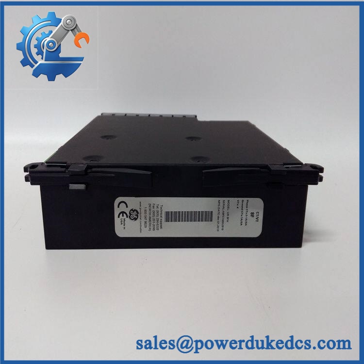
UR8GH
Quality Assurance SOP
Each available should pass a documented inspection sequence before shipment:
- OEM anti-counterfeit visual inspection: Inspect GE/Multilin markings, model designation, connector construction, PCB assembly, labels, manufacturing identifiers, and physical finish against known UR-series references.
- Part-number verification: Confirm the physical marking corresponds to and reconcile the identification with the purchase order.
- Mechanical inspection: Examine CT/VT terminals, connectors, mounting interfaces, PCB surfaces, insulation barriers, and enclosure condition for corrosion, contamination, cracks, bent contacts, or evidence of modification.
- CT/VT channel verification: On an appropriate UR test platform, verify the applicable current and voltage measurement channels and confirm that the host relay recognizes the installed module.
- CT secondary verification: Confirm that the configured test source matches the intended 1 A or 5 A CT secondary arrangement before applying test current.
- Sensitive-ground verification: Apply a controlled low-level test signal where the test fixture supports it and confirm that the relay reports the expected residual or ground-current response.
- Power-on self-test (POST): Check relay startup behavior and expected ERR/RUN indications after the module is installed in a compatible test assembly.
- Configuration verification: Review CT ratios, VT ratios, phase assignments, polarity, ground-current settings, and relevant protection elements.
- Communication handshake verification: Confirm that the host relay recognizes the installed module and that configuration software can read the associated relay data.
- Final inspection: Record model number, identification markings, physical condition, test results, packaging condition, and inspection status before shipment.
Procurement note: should be sourced against the complete host-relay configuration, not simply the model number. Before installation, verify the host relay model, complete order code, module position, firmware revision, CT/VT wiring, CT secondary rating, grounding method, and protection settings. The sensitive-ground function is particularly configuration-dependent, so a successful hardware POST does not by itself establish correct protection performance.











 Start Chat


