

Description
- Brand: GE Multilin
- Full Model Number: UR8NH
- System/Series Family: Multilin Universal Relay Series
- Core Function: Analog measurement module for acquiring CT and VT signals within a UR protection relay
- Top 3 Hardcore Specs: 6 phase CT inputs | 2 ground CT inputs | 4 VT inputs
- CT Configuration: 6 × 1 A / 5 A CT inputs
- Ground CT Configuration: 2 × 1 A / 5 A ground CT inputs
- VT Configuration: 4 VT inputs
- Application: Current and voltage acquisition for protection and metering functions
- Stock Status: New Surplus — exact hardware revision and packaging condition to be verified before shipment
Technical Product Introduction
A measurement-module failure inside a protection relay can remove multiple current or voltage channels at once. The GE UR8NH is an analog CT/VT module within the Multilin Universal Relay architecture, providing six phase CT inputs, two ground CT inputs, and four VT inputs. This channel density is suited to protection applications that require more current measurement points than a conventional three-phase CT configuration, particularly where multiple winding, feeder, or residual-current measurements are incorporated into the relay scheme.
The replacement decision should be based on the complete hardware configuration rather than the UR family name alone. The UR8NH’s CT channels are intended for 1 A or 5 A secondary circuits, while its four VT channels provide voltage acquisition for the host relay. Exact input characteristics, terminal assignments, hardware revision, and supported host CPU/firmware should be checked against the installed relay documentation before substitution (legacy UR hardware can be revision-sensitive). A matching model number is useful, but it is not by itself proof of application compatibility.
Application Scenarios & Field Realities
- For transformer protection schemes, the additional CT channels can accommodate measurement arrangements beyond a simple three-phase feeder, such as separate current measurements associated with transformer windings or protection elements. CT ratio and polarity data must match the existing relay configuration.
- When multiple ground-current measurements are required, two dedicated ground CT channels provide separate acquisition paths. That distinction matters when the protection logic uses independently configured ground-current elements rather than calculating every quantity from the phase CTs.
- Inside complex feeder and substation protection panels, four VT inputs allow the host UR relay to acquire several voltage signals alongside its current measurements. Before replacement, verify whether all four voltage channels are actually wired and how the relay software assigns them.
- During a legacy relay maintenance shutdown, the most useful preparation is often simple: photograph every connector, record the installed module identification, save the relay settings, and document the CPU and firmware revision before removing the original card. That record can prevent an otherwise avoidable configuration mismatch.
Migration, Compatibility & Installation Traps
Replacement Matrix
| Replacement Condition | Assessment | Engineering Requirement |
|---|---|---|
| Existing module is UR8NH with matching hardware configuration | Drop-in Hardware Replacement | Verify model, revision, connector assignment, CT/VT configuration, and host relay compatibility |
| UR8NH hardware revision differs from the installed unit | Software Compatible — verification required | Confirm host CPU/firmware support and validate relay configuration after installation |
| Replacing UR8NH with another UR analog module | Compatibility Review Required | Compare CT count, ground CT count, VT count, ratings, terminals, and configuration |
| Different CT secondary or input architecture | Hardware Modification Required | Recheck wiring, ratios, protection settings, and commissioning tests |
Field Traps — Watch Out
CT channel assignment can be the hidden failure point. With multiple phase and ground CT channels, moving a conductor to the wrong terminal can produce a relay that powers up normally while measuring the wrong electrical quantity. Verify every channel against the saved wiring record before energization.
CT secondary rating must match the configured application. The architecture uses 1 A/5 A CT inputs. Do not change CT wiring or relay settings simply because the replacement module physically fits. Confirm the actual CT secondary rating, ratio, polarity, and phase designation.
Never disconnect an energized CT secondary circuit. Use the site’s approved CT shorting, isolation, and lockout procedure. Protection-panel work should be performed by qualified personnel.
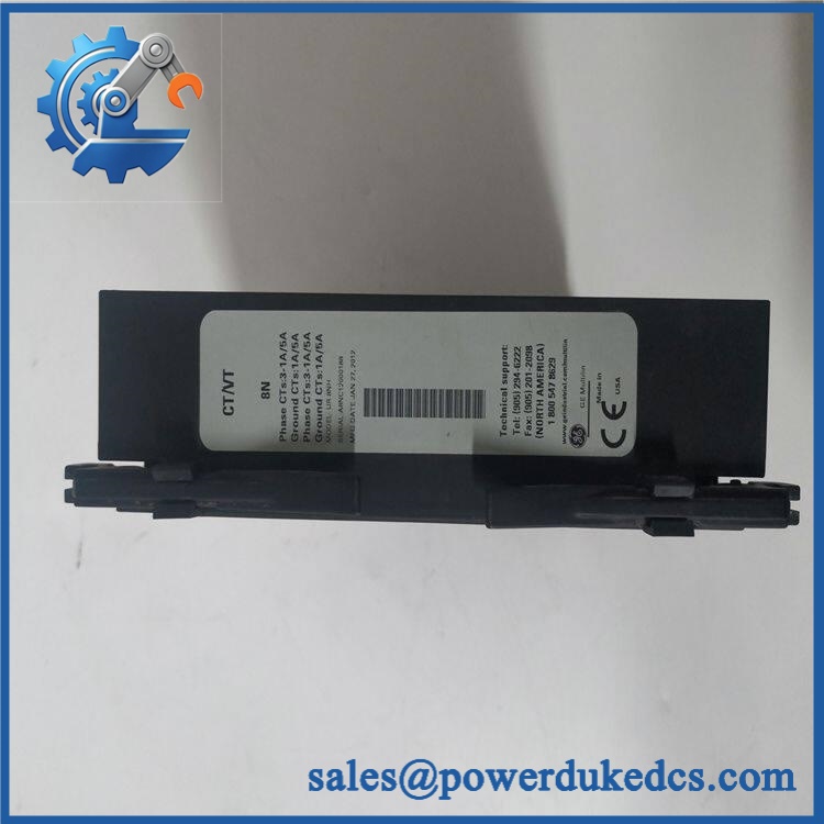
GE UR8NH
Quality Assurance SOP
Before shipment, each available unit should pass a documented inspection sequence:
- OEM anti-counterfeit visual inspection — Verify GE/Multilin markings, identification, labels, connector construction, PCB layout, and visible manufacturing identifiers.
- Channel configuration inspection — Confirm the expected architecture of 6 phase CT inputs, 2 ground CT inputs, and 4 VT inputs.
- PCB condition inspection — Examine the board for corrosion, contamination, cracked components, damaged solder joints, heat discoloration, and evidence of unauthorized repair.
- Connector inspection — Check every connector and terminal interface for bent contacts, oxidation, mechanical damage, or loose hardware.
- Host-relay recognition test — Where a compatible UR test platform is available, install the module and verify that the host relay recognizes the hardware without an I/O or configuration fault.
- CT input verification — Apply controlled test signals to each phase and ground CT channel using an appropriate protection-relay test system. Verify channel identity and measured values independently.
- VT input verification — Apply controlled test voltage to each VT channel and confirm that the host relay reports the correct voltage input.
- Channel mapping verification — Confirm phase designation, ground-current assignment, CT ratio, CT secondary selection, VT ratio, and associated protection settings against the customer’s original configuration.
- Diagnostic verification — Review the host relay diagnostic/status information for hardware faults, abnormal input readings, or configuration errors.
- Final visual inspection — Photograph the actual nameplate, connectors, and overall condition before packing.
- Packaging inspection — Record whether the unit is factory sealed, original packaging, or surplus packaging. Protect connectors and PCB surfaces against ESD and mechanical impact.
- Shipment release — Any discrepancy between the ordered configuration and the inspected physical unit stops shipment until resolved.











 Start Chat


