

Description
- Brand — GE
- Full Model Number — VME-1064
- System/Series Family — GE VMEbus / GE Fanuc VMIC Embedded Computing
- Core Function — High-speed fiber-optic memory interface module for VME-based embedded computing and data-transfer architectures
- Top 3 Hardcore Specs — Fiber-optic memory interface; VME-based board architecture; PCB identifier reported as 101864 Rev-2
- Stock Status — New Surplus or Tested Stock — exact unit condition to be confirmed before shipment
Current technical listings identify the GE VME-1064 as a high-speed fiber-optic memory module. A separate hardware listing associates the model with board marking 101864 Rev-2. Publicly available sources do not provide a sufficiently reliable OEM figure for memory capacity or optical link speed, so those values should be verified from the physical board or applicable GE documentation before being placed on a purchase specification.
Technical Product Introduction
When a VME embedded computer depends on a dedicated optical data path, a failed memory interface board can stop high-rate data exchange even though the host CPU itself still boots normally. The GE VME-1064 is identified as a high-speed fiber-optic memory module intended for this class of VME-based architecture. That makes it a maintenance component rather than a generic RAM expansion card. GE Fanuc’s wider VME product family includes CPU boards, storage devices, I/O cards, serial expansion cards, and fiber-based bus interfaces operating inside VME chassis.
The practical engineering value lies in preserving the original board-level architecture. A replacement with the identical VME-1064 order code avoids automatically changing the host software stack or redesigning the VME backplane arrangement. The publicly documented identifier 101864 Rev-2 is useful when checking incoming inventory against installed hardware. One important limitation remains: reliable public documentation for the VME-1064’s exact optical bitrate, memory capacity, connector specification, and supported fiber type was not found. Those parameters should therefore be treated as OEM documentation to be verified, not filled with estimated numbers.
Application Scenarios & Field Realities
- In VME-based test and measurement equipment, optical memory interfaces can be used where large data sets must move between acquisition hardware and the host processing section without extending copper buses across a noisy cabinet. GE/FANUC VME systems are documented in scientific instrumentation using fiber-based VME interfaces and dedicated memory cards.
- For embedded data-processing cabinets, the VME-1064 is relevant when the existing hardware stack already depends on a dedicated optical memory path. Replacing the board with the exact part number is usually less disruptive than substituting a different VME card and changing the host application.
- During legacy VME system refurbishment, technicians should compare the actual PCB marking before ordering. The has been listed with 101864 Rev-2, making board revision an important receiving-inspection field rather than a cosmetic detail.
- Where fiber links pass between separate equipment sections, optical transmission can avoid some of the grounding and electromagnetic-coupling problems associated with long copper interconnects. The exact optical topology still matters — especially fiber type, transceiver characteristics, and connector arrangement — and those details must be checked against the installed system.
Migration, Compatibility & Installation Traps
Replacement Matrix
| Replacement Case | Classification | Engineering Requirement |
|---|---|---|
| replacing the same | Drop-in Replacement | Match model number and board revision; verify VME slot position and optical connections before startup |
| replaced by another GE optical memory board | Software Compatible | Host configuration and driver behavior must be checked; optical interface characteristics may differ |
| replaced by a different VME architecture | Hardware Modification Required | Evaluate backplane interface, memory mapping, optical interface, software drivers, and application integration |
The most important compatibility point is not the fact that both boards use VME. VME bus compatibility alone does not prove application compatibility. Board address mapping, interrupt behavior, memory windows, optical interface type, and host software support can all affect whether an alternative board will operate correctly. GE/FANUC VME systems include a wide range of processor, I/O, memory, and fiber-interface boards, so the installed chassis configuration must be considered as a complete system.
Field Traps — Watch Out
Fiber specification mismatch: Never assume that an available patch cable or transceiver is suitable because the connector appears identical. Confirm single-mode versus multimode requirements, wavelength, optical budget, connector type, and transmit/receive orientation from the installed hardware documentation. The public data reviewed for does not establish these values reliably.
Board revision mismatch: A listing referencing 101864 Rev-2 should prompt a direct comparison with the installed board. Older and later revisions can have electrical or firmware dependencies even when the front designation remains similar. Record the PCB identifier before removing the failed unit.
VME insertion and ESD: Power down the VME chassis unless the specific system documentation explicitly permits live insertion. Protect the card edge connector and optical interface from ESD and contamination. A visibly clean fiber connector can still introduce substantial optical loss when microscopic contamination is present.
Host recognition: After installation, confirm that the VME host recognizes the board and that the expected address space or memory resource is available. Do not judge the replacement successful solely because the chassis powers up.
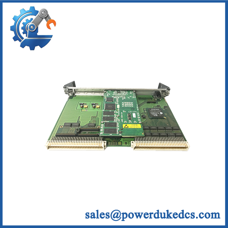
GE VME-1064
Quality Assurance SOP
The pre-shipment procedure should focus on board authenticity, physical integrity, VME host recognition, and the optical data path:
- OEM anti-counterfeit visual inspection — compare the GE model marking, PCB layout, board identifier, revision marking, component population, connector construction, labels, and evidence of rework against known reference hardware.
- PCB revision verification — record the visible board identifier and confirm whether the unit carries the expected 101864 Rev-2 marking where applicable.
- Mechanical inspection — inspect the card edge connector, VME interface pins, optical connectors, mounting hardware, PCB surface, and shielding for damage, corrosion, contamination, or bent contacts.
- Power-on self-test (POST) — install the module into an appropriate VME test chassis and verify normal system startup. Where diagnostic indicators are provided, inspect the expected ERR/RUN or status indications and record abnormal states.
- VME host recognition verification — confirm that the host CPU detects the board and that the expected board resources can be accessed without bus errors.
- Memory-path verification — perform controlled read/write or data-buffer testing through the supported host interface where the test environment provides access to the module’s memory function.
- Communication handshake verification — verify the associated optical data path or host-to-module handshake where the system architecture exposes this diagnostic function. If the available test bench cannot exercise the optical interface, that limitation should be recorded rather than represented as a completed test.
- Optical interface inspection — inspect connectors and ports with suitable fiber-cleaning procedures before testing; verify transmit/receive continuity using the applicable system test equipment.
- Final QA record — photograph the actual unit, capture model and revision information, document test results, apply ESD protection, cap optical ports, and package the board for shipment.
For a legacy VME board such as the , the useful acceptance standard is not simply “board powers on.” The unit should be positively identified, recognized by the intended VME host, and tested through the available memory and optical data path to the level supported by the test bench. Public references consistently associate the with a fiber-optic memory function, while detailed electrical and optical specifications remain insufficiently documented in the sources reviewed.











 Start Chat


