

Description
- Brand: GE
- Full Model Number: VME-MB-Z004
- System/Series Family: GE VME / GE Fanuc VME-based control hardware
- Core Function: Passive VME backplane providing mechanical mounting and electrical interconnection for VME boards
- Top 3 Hardcore Specs: 4 VME slots; 6U Eurocard format; IEEE 1014 VME bus architecture
- Stock Status: New Surplus — unit condition, revision, and current availability to be verified
Available technical records identify GE VME-MB-Z004 as a 4-slot VME backplane for VME-based control hardware, with 6U board positions and a passive interconnection role. Published descriptions associate the board with the IEEE 1014 VME architecture.
Technical Product Introduction
A failed backplane can create a particularly difficult maintenance problem: individual CPU, communication, and I/O boards may test normally on the bench while the assembled rack still shows intermittent or missing communication. The GE VME-MB-Z004 serves as the common electrical and mechanical interface between VME plug-in boards. Available records describe a 4-slot passive backplane intended for GE VME-based systems, rather than a processor or application-specific I/O card.
The key specification is slot capacity. This version is described with four 6U VME positions, using the standard Eurocard form factor associated with VME systems. Published records also identify the VME bus as the interconnect standard and list support for the associated power rails supplied by the host chassis. The important purchasing issue is configuration matching, not a generic claim of universal compatibility. —Public listings for this part are inconsistent and sometimes assign unrelated functions to the same model number, so the nameplate, connector layout, and existing chassis arrangement should be checked before PO release.
Application Scenarios & Field Realities
- Legacy VME control racks: When a VME CPU and I/O boards work individually but the assembled rack develops bus-related faults, the backplane becomes a primary inspection point. Loose card guides, oxidized connector contacts, or damaged bus traces can affect several boards at once.
- Power-system control and protection cabinets: In older VME-based installations, the backplane may carry the common connection between processing, communications, and application cards. Replacing a damaged backplane can preserve the existing board set without forcing a complete architecture change, provided the slot arrangement and connector topology match the original unit.
- Industrial test and measurement platforms: A multi-slot VME chassis is often assembled around several functional boards sharing the same bus. Here, a backplane fault may appear as a board-level failure even when the actual problem is loss of a bus line or an unstable power connection.
- Long-life maintenance programs: For obsolete VME equipment, the physical condition of the backplane deserves more attention than its age alone. Inspect the card connectors and solder joints carefully; a backplane can look clean externally while exhibiting intermittent faults under vibration or thermal cycling.
Migration, Compatibility & Installation Traps
Replacement Matrix
| Replacement Type | Assessment |
|---|---|
| Drop-in Replacement | Yes, when the existing chassis uses the same VME-MB-Z004 configuration and connector arrangement |
| Software Compatible | Not normally applicable to a passive backplane; compatibility is primarily electrical and mechanical |
| Hardware Modification Required | Normally no for an exact same-model replacement |
The VME-MB-Z004 should be treated as a system-level passive interconnect, not as a CPU or intelligent communication module. Available product documentation describes four 6U VME slots and an IEEE 1014-based VME architecture. Because online records for this exact model are inconsistent, exact replacement should be based on the installed unit’s connector arrangement, slot spacing, chassis dimensions, mounting points, and revision markings.
Field Traps — Watch Out
Connector contamination: VME edge connectors carry multiple bus and power contacts. A small amount of oxidation or contamination can create intermittent faults that resemble a failed CPU or I/O board. Clean and inspect contacts according to the equipment manufacturer’s approved procedure before blaming an installed module.
Bus termination and slot arrangement: Do not change slot positions or install an incompatible VME board merely because its mechanical dimensions match. Confirm the original chassis architecture, bus configuration, and any board-specific termination requirements before powering the rack.
Power-rail verification: A backplane distributes chassis power to installed boards. Measure the relevant supply rails at the backplane under load before commissioning; a marginal power connection can produce multiple unrelated board alarms.
Revision identification: Verify the full part marking, not just “VME-MB-Z004.” The same basic model reference can appear in inconsistent distributor records, including descriptions that do not agree on the product function.
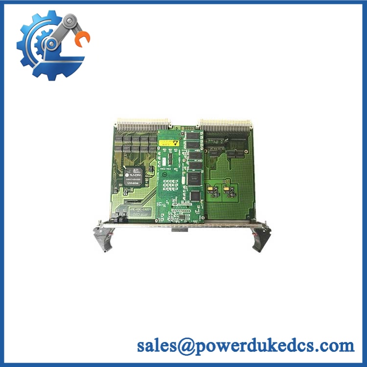
GE VME-MB-Z004
Quality Assurance SOP
For surplus inventory, QA should concentrate on the passive electrical path, connector condition, and dimensional match.
- OEM anti-counterfeit visual inspection: Verify GE identification labels, part number, board markings, connector arrangement, revision information, and overall construction against the expected configuration.
- Mechanical inspection: Check the PCB for cracks, warpage, impact marks, contamination, corrosion, lifted pads, damaged guides, and evidence of unauthorized repair.
- Connector inspection: Examine every VME connector for bent contacts, damaged housings, oxidation, contamination, or poor mechanical retention.
- Backplane continuity test: Verify continuity across the relevant VME bus and power distribution paths using a controlled test procedure and approved pinout documentation.
- Power distribution verification: Confirm that the expected chassis supply rails reach the appropriate backplane positions without abnormal resistance, shorts, or excessive voltage drop.
- Slot-by-slot inspection: Check all four VME positions individually for mechanical alignment and connector integrity.
- System-level handshake verification: Install the backplane in a compatible VME chassis with known-good CPU, communication, and I/O cards, then verify normal board recognition and bus communication.
- Loaded operating check: Operate the assembled chassis through the defined QC period and monitor for intermittent resets, communication loss, abnormal heating, or bus errors.
- Final traceability check: Record model number, revision, serial or identification information where available, test date, continuity results, system-test results, and shipment condition.
For procurement, the safest identification is GE , 4-slot 6U VME passive backplane based on the available technical record. Since public references for this part are not fully consistent, a clear photo of the nameplate and rear connector side should be used as the final verification reference before shipment.











 Start Chat


