

Description
- Brand: GE
- Full Model Number: VME7865RC
- Board Number: V7865-23003
- GE Part Number: 350-9300007865-230003
- System/Series Family: VMEbus Embedded Computing
- Core Function: Single-board computer for VMEbus-based embedded and industrial computing systems
- Top 3 Hardcore Specs: Pentium M processor | 6U single-slot VMEbus format | VMEbus backplane architecture
- Form Factor: 6U VME single-slot board
- Cooling: Passive cooling reported
- Stock Status: New surplus or fully tested refurbished subject to exact inventory confirmation
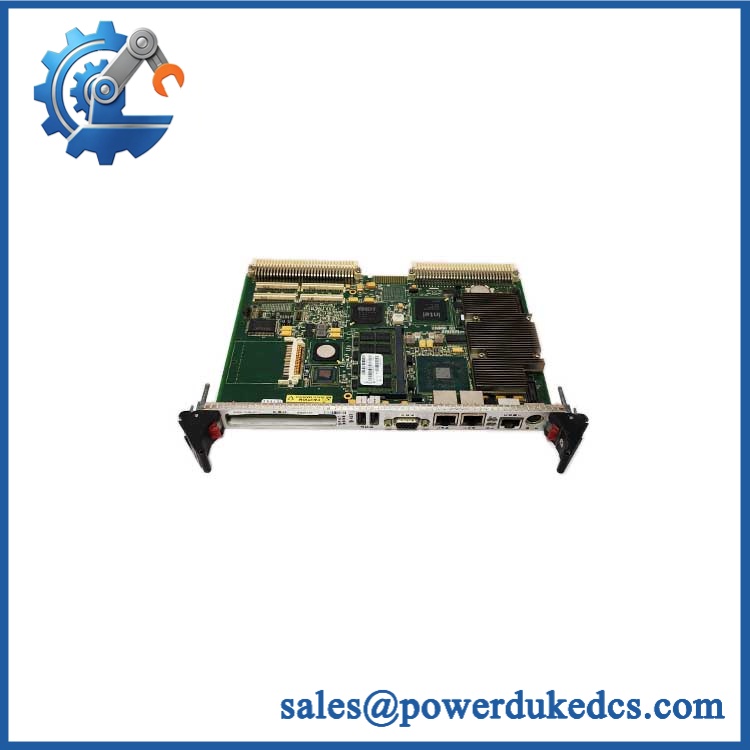
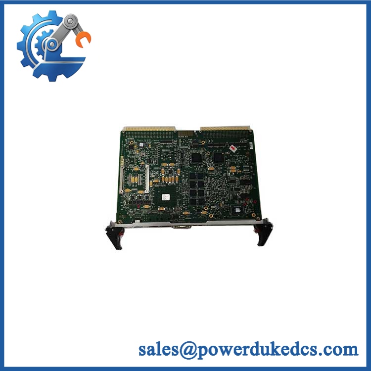
The GE VME7865RC is identified by the ordering references V7865-23003 and 350-9300007865-230003. Available records describe it as a Pentium M-based single-board computer using a single-slot VME Eurocard architecture.
Module 3: Technical Product Introduction
A failed VME controller board can stop an embedded control chassis even when the backplane, I/O cards, and application hardware remain serviceable. The GE VME7865RC V7865-23003 is a VMEbus single-board computer intended to provide processing resources within a VME-based system. Available product records identify the board as a Pentium M-based SBC and associate it with the 350-9300007865-230003 part number. Its single-slot VME Eurocard format is particularly important during replacement because mechanical compatibility with the existing chassis is part of the installation requirement.
The board is reported as a 6U single-slot VMEbus design with passive cooling. That architecture makes the backplane interface, board revision, processor configuration, and installed software environment more important than generic “computer board” specifications. Some secondary listings incorrectly describe the VME7865RC as a digital I/O module or even an excitation-control device; those descriptions conflict with the available SBC documentation and should not be used for engineering selection.
Module 4: Application Scenarios & Field Realities
- In legacy VME industrial controllers, the VME7865RC can serve as the central computing element while other VME cards provide I/O, communications, or specialized processing. Before replacement, identify every board occupying the same chassis and record the original slot arrangement.
- For embedded control systems requiring deterministic VMEbus communication, the backplane configuration matters. A board can power up correctly while still failing to communicate with another VME card because of address-space, interrupt, or software configuration differences.
- During a scheduled maintenance outage, preserve the existing operating environment before removing the CPU board. Record BIOS settings, installed operating system details, application storage, VME address assignments, and network parameters where accessible.
- On long-running legacy systems, passive cooling deserves a practical inspection. Dust accumulation around the chassis airflow path can raise board temperature even when the CPU itself remains within its rated operating range. Check the complete enclosure, not just the replacement card.
GE VME7865RC V7865-23003
Module 5: Migration, Compatibility & Installation Traps
Replacement Matrix
| Replacement Type | Assessment | Engineering Requirement |
|---|---|---|
| Drop-in Replacement | Potentially yes for an identical VME7865RC configuration | Match V7865-23003, 350-9300007865-230003, board revision, and chassis requirements |
| Software Compatible | Configuration-dependent | Verify operating system, BIOS, application image, VME drivers, and hardware configuration |
| Hardware Modification Required | Not normally expected for an exact same-board replacement | Confirm 6U VME chassis, slot depth, backplane, and cooling arrangement |
Field Traps — Watch Out
1. Do not confuse with VME I/O hardware: One secondary source incorrectly categorizes as a high-density digital I/O module, while other records identify it as a Pentium M VMEbus single-board computer. The latter classification is consistent with the V7865-23003 references and VME SBC documentation.
2. Exact board identification matters: The references , V7865-23003, and 350-9300007865-230003 M should be recorded together. A similar-looking VME CPU board is not automatically compatible with the existing application.
3. Software image risk: Replacing the hardware without preserving the existing operating environment can create a longer outage than the original hardware failure. If the old board still boots, capture application files, network settings, BIOS configuration, and required drivers before removal.
4. VME backplane configuration: Confirm slot assignment, VMEbus addressing, interrupt configuration, and any board-specific jumper or switch settings against the original installation. Do not alter the backplane configuration merely to accommodate a replacement board unless the system documentation requires it.
GE VME7865RC V7865-23003
Module 6: Quality Assurance SOP
Before shipment, each GE V7865-23003 / 350-9300007865-230003 should undergo a documented board-level inspection sequence.
- Step 1 — Part-number verification: Record , , 350-9300007865-230003, revision information, serial number, and all visible GE identification markings.
- Step 2 — OEM anti-counterfeit visual inspection: Examine GE labels, PCB markings, processor identification, connectors, VMEbus edge connector, memory devices, fasteners, and manufacturing identifiers. Photograph the complete board and nameplate.
- Step 3 — Physical condition inspection: Check the PCB for corrosion, contamination, cracked components, bent connector contacts, damaged edge fingers, loose hardware, and evidence of previous repair.
- Step 4 — Power-rail verification: Before full startup, verify that the test fixture supplies the correct VME chassis power and that no abnormal short or excessive current draw is present.
- Step 5 — Power-on self-test (POST): Energize the board in an appropriate VME test chassis and record processor initialization, BIOS/firmware behavior, memory detection, diagnostic codes, and available status indicators.
- Step 6 — VMEbus verification: Install the board in a compatible test chassis and verify that the system recognizes the board and that expected VMEbus transactions can be completed.
- Step 7 — Memory and processor verification: Confirm processor initialization and available memory recognition during POST or the appropriate diagnostic procedure.
- Step 8 — Communication handshake verification: Where the required test environment is available, verify applicable network or serial interfaces and confirm communication with representative system hardware.
- Step 9 — Operating-environment verification: Where authorized and technically possible, boot the appropriate operating environment and verify application-level initialization without modifying customer-specific data.
- Step 10 — Final photographic record: Photograph the complete board, part-number labels, processor area, connectors, VME edge connector, revision markings, and final packaging.
QA release criterion: A successful POST confirms basic board initialization but does not prove compatibility with a customer’s VME application. For a complete replacement claim, the exact / 350-9300007865-230003 hardware identity and the customer’s VME/software configuration should be matched first.











 Start Chat


