

Description
-
- Brand: GE / VMIC
- Full Model Number: VMIVME-4140
- System/Series Family: VMIC VME Analog I/O
- Core Function: 32-channel 12-bit analog output board for VMEbus control and data acquisition systems
- Top 3 Hardcore Specs: 32 analog outputs; 12-bit DAC per channel; up to 10 mA output current
- Output Ranges: 0 to +2.5 V; 0 to +5 V; 0 to +10 V; ±2.5 V; ±5 V; ±10 V
- Output Impedance: 0.8 Ω
- Update Method: Random nonscanning; software or external synchronous update
- Calibration: Automatic calibration after reset or software command
- Stock Status: New Surplus or Fully Tested Refurbished subject to unit-specific availability
The is documented as a 32-channel, 12-bit analog output VME board with one DAC per output channel and selectable unipolar or bipolar voltage ranges. GE documentation specifies a maximum output current of 10 mA per channel and 0.8 Ω output impedance.
Technical Product Introduction
When a legacy VME controller still runs the application but one analog output card begins producing incorrect setpoints, replacing the whole control rack is often unnecessary. The GE provides 32 analog output channels on the VMEbus, with a dedicated 12-bit DAC for each channel. Output ranges are software selectable across 0 to +2.5 V, 0 to +5 V, 0 to +10 V, ±2.5 V, ±5 V, and ±10 V. Outputs can be updated randomly rather than through a fixed scanning sequence, and double-buffered operation supports software or externally synchronized updates.
For process-control engineers, the important distinction is per-channel conversion rather than headline bus speed. Each of the 32 outputs has its own 12-bit converter, while the board can source or sink up to 10 mA depending on the configured application. Automatic calibration can be initiated by reset or software command, reducing manual adjustment work during maintenance. The analog output connector and reference-voltage access are available at the front panel, and the design includes onboard self-test functions. —the exact field wiring still has to match the installed connector and cable configuration.
Application Scenarios & Field Realities
- In closed-loop process-control cabinets, the can generate analog command signals for valve positioners, drives, current-to-pressure interfaces, or other analog actuators. The 12-bit resolution provides 4096 discrete output codes per selected voltage range, so scaling should be checked against the control application’s engineering-unit conversion.
- For laboratory and automatic test equipment, random channel updates are useful when several stimulus channels must change independently rather than following a sequential scan. The board’s software or external synchronous update capability also suits test sequences that require multiple outputs to change at a controlled update event.
- Where an existing VME data-acquisition rack controls analog test points, the dedicated DAC-per-channel architecture simplifies channel-level verification. A failed channel can be isolated during troubleshooting while the remaining outputs stay under application control.
- During maintenance of long-lived VME installations, onboard self-test becomes especially practical. GE documentation notes that outputs can be disconnected from field wiring for offline testing, allowing technicians to distinguish a board-side conversion problem from a downstream wiring or actuator fault. PMC expansion slots are also part of the documented board feature set.
Migration, Compatibility & Installation Traps
Replacement Matrix
Replacement Condition Classification Engineering Guidance Existing replaced with the same hardware configuration Drop-in Replacement Normally the lowest-impact substitution when the VME chassis, address settings, connector arrangement, and software scaling remain unchanged Replacing a with another board in the same VME analog-output family Software Compatible Verify channel count, resolution, voltage range, register map, calibration behavior, and application scaling before commissioning Converting from to a different bus architecture or different analog-output platform Hardware Modification Required Expect changes to chassis hardware, cabling, I/O mapping, drivers, and application configuration Field Traps:
Connector and cable configuration. The supports discrete-wire and mass-terminated cable arrangements. A board can be electrically correct yet still fail a replacement job when the existing interface cable does not match the installed connector arrangement. Verify the original board, cable assembly, and termination hardware as a set before installation.
Voltage-range and load mismatch. The six documented output ranges are not interchangeable from a commissioning perspective. A process loop scaled for ±10 V should not be assumed to behave correctly after software is changed to a 0 to +10 V range. Also check the downstream load before energizing; the published maximum output current is 10 mA per channel.
Address and software assumptions. Retain the original VME address configuration and application channel mapping before removing the failed card. The replacement should be validated against the controller’s actual register access sequence rather than relying only on the model number.
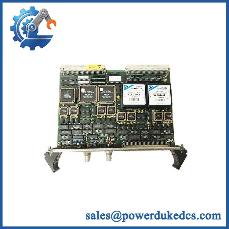
GE VMIVME-4140
Quality Assurance SOP
Each unit enters inspection with identification and physical-condition checks. The QA process includes an OEM anti-counterfeit visual inspection covering model markings, PCB revision information, connector condition, component placement, solder quality, mounting hardware, and evidence of unauthorized rework. Configuration details are recorded before electrical testing so a replacement is not approved merely because the front-panel label matches.
Testing begins in a compatible VME chassis with controlled power-up. The board is checked for abnormal indications and stable VMEbus operation, followed by a power-on self-test (POST) checking for available board-status indications and execution of the manufacturer’s supported self-test functions. Because the is an analog-output board rather than a CPU module, QA does not invent a processor-style ERR/RUN sequence; the test record instead captures the actual board status behavior and diagnostic result. The documented self-test capability allows the analog outputs to be isolated from field wiring during testing.
A communication handshake verification is then performed at the VMEbus level, confirming address recognition, register access, command response, and deterministic channel updates. All available analog channels are exercised against calibrated measurement equipment, with output values checked at representative unipolar and bipolar ranges. Calibration behavior is also verified because the board supports automatic calibration after reset or software command. Final QA records include channel test results, measured output values, board identification, visible condition, and packaging inspection before shipment.











 Start Chat


