

Description
- Brand: GE Fanuc Embedded Systems
- Full Model Number: VMIVME-7807
- System/Series Family: VMIVME VMEbus Single Board Computer family
- Core Function: 6U single-slot Pentium M VMEbus computer for industrial control, data acquisition, test, simulation, and legacy embedded computing
- Top 3 Hardcore Specs: Up to 1.8 GHz Intel Pentium M; up to 1.5 GB DDR SDRAM; PCI-X 64-bit 66 MHz PMC expansion
- VMEbus Interface: Universe II PCI-to-VMEbus interface; A16/A24/A32 addressing; BLT32/BLT64; programmable requester and arbiter
- Network: 10/100 Ethernet plus dual Gigabit Ethernet configuration options
- Storage: Serial ATA; ATA-33/66/100 IDE; up to 2 GB CompactFlash option
- I/O: 4 × USB 2.0; 4 × 16550-compatible serial ports; SVGA; rear-I/O DVI
- Form Factor: 6U single-slot Eurocard
- Stock Status: New Surplus subject to exact configuration and physical-unit verification
The original VMIVME-7807 specification lists 1.1, 1.6, and 1.8 GHz Pentium M processor options, up to 1.5 GB DDR SDRAM, a 66 MHz PCI-X PMC site, four USB 2.0 ports, four serial ports, and optional CompactFlash.
Technical Product Introduction
When the CPU board is the failed element in an established VME chassis, replacing the entire control architecture can create unnecessary software, I/O, and commissioning work. GE Fanuc’s VMIVME-7807 is a 6U single-slot VMEbus SBC built around the Intel 855GME chipset and Pentium M processor family. Depending on the ordering configuration, processing is available at 1.1, 1.6, or 1.8 GHz, with up to 1.5 GB DDR SDRAM. The board also integrates a Universe II PCI-to-VMEbus interface, 10/100 Ethernet, Gigabit Ethernet options, SVGA, rear-I/O DVI, serial interfaces, USB 2.0, SATA, IDE, and a PMC expansion site.
The useful engineering numbers are specific. The 1.6 GHz and 1.8 GHz configurations require +5 VDC with 7.28 A typical and 9.1 A maximum consumption; the documented operating range is 0 to 50 °C when the heatsink airflow exceeds 450 LFM. The board measures approximately 233.4 × 160 × 20.3 mm and stores 32 KB in nonvolatile SRAM. A maximum 1.5 GB DDR configuration is available, while the processor options provide up to 2 MB of L2 cache. For an aging VME platform, retaining the established 6U mechanical format, VMEbus address model, serial interfaces, and legacy storage paths can materially reduce the scope of a replacement project.
Application Scenarios & Field Realities
- Factory test systems: Where a VME chassis runs an older test application while communicating with instruments over serial ports, the four 16550-compatible serial channels and PC-oriented operating-system support are important. COM1 is available from the front panel, while COM2, COM3, and COM4 are routed toward rear I/O and can be configured for RS-232/422. That matters when the original rack wiring was built around the P2 connector.
- Data acquisition racks: In a data acquisition system using VME interrupts and direct shared memory, the board’s VME interface supports A16, A24, and A32 addressing plus BLT32 and BLT64 transfers. Byte-swapping is handled in hardware, with independent master and slave control. During a replacement, preserving the existing address map and endian-handling assumptions is far more important than processor clock speed alone.
- Industrial process monitoring: For a process-monitoring computer that boots from local storage or CompactFlash, the VMIVME-7807 provides ATA-33, ATA-66, and ATA-100 IDE support, with BIOS support for booting from CompactFlash. An older disk image may therefore remain usable, but the exact storage device, connector routing, and BIOS configuration need to be checked before installation.
- Simulation and instrumentation platforms: A VME controller used for simulation can take advantage of the single PMC site when specialized PCI/PCI-X I/O is required. The PMC interface is specified for 64-bit PCI-X at up to 66 MHz; older 33 MHz/32-bit PMC cards cause the bus to throttle to the legacy card’s capability — an easy point to miss during a board replacement.
Migration, Compatibility & Installation Traps
Replacement Matrix
| Replacement Condition | Classification | Engineering Requirement |
|---|---|---|
| Exact VMIVME-7807 model with matching processor, memory, P0, ECC, and other ordering options | Drop-in Replacement | Verify the complete configuration before installation; identical model family alone is not sufficient |
| VMIVME-7807 with different processor or memory option but same application architecture | Software Compatible | Validate BIOS settings, installed operating system, VME memory mapping, drivers, storage image, and application behavior |
| Different VME CPU architecture or transition to another board family | Hardware Modification Required | Review software, P2/P0 rear-I/O wiring, storage, PMC hardware, chassis configuration, and VME system-controller settings |
The original ordering structure allows different CPU speeds, DDR capacities, CompactFlash capacities, P0 configuration, ECC support, and special front-panel or conformal-coating options. Consequently, the full ordering configuration should be checked before treating two boards as interchangeable.
Field Traps to Watch
P0 and VITA 31.1 mismatch: The dual Gigabit Ethernet routing changes with the P0 configuration. Some configurations route the interfaces through the front panel or P2, while the optional P0 implementation supports the VITA 31.1 interface. A chassis designed around P0 rear routing cannot be assumed to work correctly with a board lacking that configuration.
Cooling and PMC behavior: The passive heatsink depends on forced cabinet airflow, with the specification requiring more than 450 LFM at the heatsink outlet for the standard 0 to 50 °C operating range. Also, a legacy 33 MHz/32-bit PMC card causes the PCI-X 66 MHz/64-bit bus to throttle back. Both conditions should be checked before declaring a replacement successful. —Especially in densely populated VME racks.
ATA-100 cable requirement: When ATA-100 operation is required, the documentation specifies an 80-conductor cable rather than the standard 40-conductor cable. Reusing the wrong cable can create a storage-detection or transfer-mode problem that may initially look like a processor-board fault.
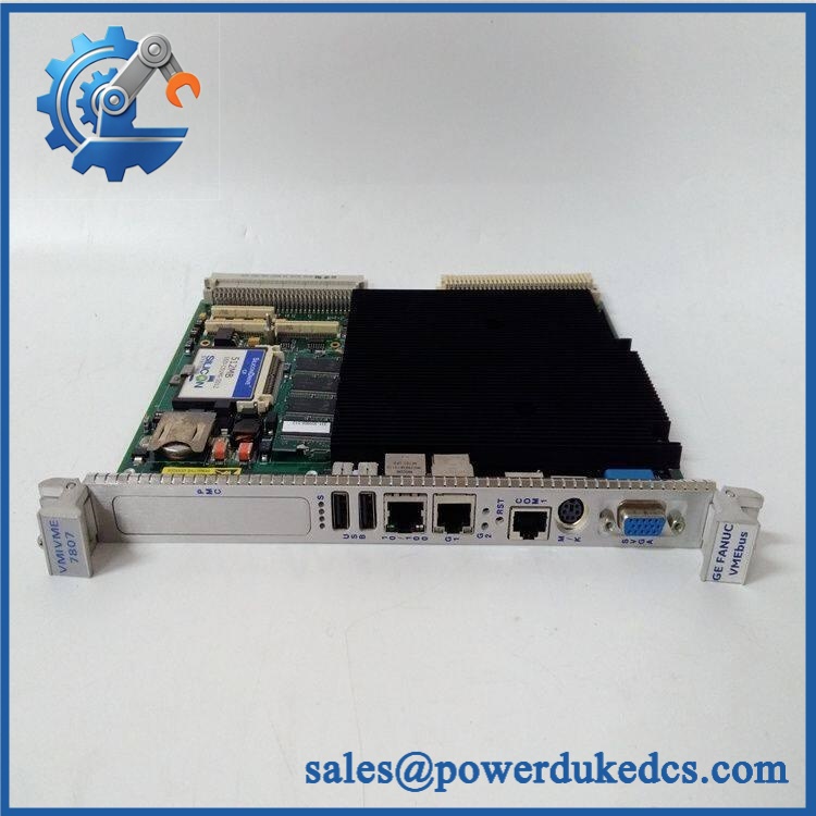
GE VMIVME-7807
Quality Assurance SOP
The pre-shipment inspection for a should be performed as a controlled board-level verification rather than relying only on visual condition.
- OEM anti-counterfeit visual inspection: Verify GE Fanuc/VMIVME identification, PCB markings, labels, component population, connector condition, board revision, and visible assembly details against the expected configuration.
- Mechanical inspection: Examine the 6U PCB, VMEbus connectors, front-panel interfaces, PMC connector, rear-I/O interfaces, mounting hardware, and heatsink assembly for bent pins, corrosion, cracked material, contamination, or impact damage.
- Power-on self-test (POST): Apply controlled +5 VDC power and record BIOS/POST behavior, CPU initialization, memory detection, video initialization, and available status indicators.
- Memory verification: Confirm the installed DDR SDRAM capacity and, where applicable, ECC configuration against the unit’s stated ordering option.
- Communication handshake verification: Test the available Ethernet interfaces and serial channels with controlled loopback or known-good equipment. Verify COM1 and relevant rear-I/O serial channels according to the actual configuration.
- VMEbus functional verification: Confirm VMEbus master/slave access, interrupt handling, address mapping, and data-transfer operation with a compatible test chassis. The Universe II interface supports programmable requester, arbiter, interrupt, and byte-swapping functions.
- USB and display check: Verify front/rear USB 2.0 operation where accessible, together with SVGA output. Rear-I/O DVI should be checked when the supplied configuration and test fixture support it.
- Storage verification: Confirm IDE/SATA/CompactFlash recognition where the relevant hardware is fitted. For ATA-100 testing, use the specified 80-conductor cable.
- Thermal check: Confirm heatsink installation and cabinet airflow conditions. The documented standard operating requirement is greater than 450 LFM at the heatsink outlet.
- Final QA record: Record exact model/configuration markings, test results, visible condition, installed memory, processor option, storage option, and final packing condition before shipment.











 Start Chat


