

Description
- Brand — GE
- Full Model Number — WESCOM D200 VME
- System/Series Family — WESCOM D200 VME Control System
- Core Function — VME-based industrial control platform for distributed process and equipment control
- Top 3 Hardcore Specs — VMEbus architecture; modular processor and I/O design; D200 control-system platform
- Stock Status — New Surplus / availability subject to physical inventory confirmation
Technical Product Introduction
A legacy VME control system is rarely just a single processor card. The backplane, CPU, I/O modules, application software, and configuration data have to work as one system. GE WESCOM D200 VME refers to a GE industrial control architecture built around the VMEbus platform. Available technical records associate the D200 system with modular control hardware and WES5123-series processor modules. That makes the exact card number and board revision important when sourcing a replacement.
From a maintenance perspective, the value of retaining the original D200 architecture is straightforward: existing field wiring and application logic may remain in service without forcing a complete controls migration. The technical details of an individual VME assembly—processor type, memory, I/O capacity, communication interfaces, and firmware—depend on the specific module installed. Publicly available secondary listings do not provide a single consistent specification set for the complete WESCOM VME system, so those parameters should be verified against the equipment nameplate and applicable GE documentation before purchase.
Application Scenarios & Field Realities
- In legacy process-control cabinets, a VME system can remain the central control platform while individual processor or I/O cards are replaced as failures occur. Record the rack layout before removing any card; VME slot position can matter.
- For plants with large installed bases of older GE control equipment, maintaining matching processor and I/O spares can reduce the scope of an unplanned repair. Keep board revisions documented alongside the spare inventory.
- Where multiple I/O cards share a common VME backplane, troubleshooting should begin with power rails and bus integrity before assuming a failed CPU. A dark or non-booting processor does not automatically mean the processor itself is defective.
- During a planned modernization, the VME platform can serve as the baseline for determining which functions must be migrated. Identify I/O points, application logic, communication interfaces, and field-device dependencies before selecting a successor architecture.
Migration, Compatibility & Installation Traps
Replacement Matrix
| Replacement condition | Assessment | Engineering requirement |
|---|---|---|
| Identical VME module and revision | Drop-in Replacement | Verify part number, board revision, slot assignment, and configuration |
| Same family with different hardware revision | Software Compatible After Verification | Check firmware, application image, memory, and peripheral compatibility |
| Different control-system platform | Hardware Modification Required | Re-engineer I/O, communications, application logic, and cabinet interfaces |
Field Trap 1 — VME slot and backplane configuration:
Do not move a processor or interface card to another slot simply because the connector fits. Document the original rack position, neighboring cards, termination arrangements, and backplane configuration before replacement.
Field Trap 2 — Firmware/application dependency:
A replacement board can pass its basic power-up test yet fail to load the plant application. Preserve the existing firmware, boot media, configuration files, and application image before removing a functioning processor.
Field Trap 3 — System-level identification:
“WESCOM VME” describes a platform rather than necessarily identifying one unique replaceable board. For procurement, request the exact GE board number, revision, and nameplate information. This avoids treating different VME assemblies as interchangeable.
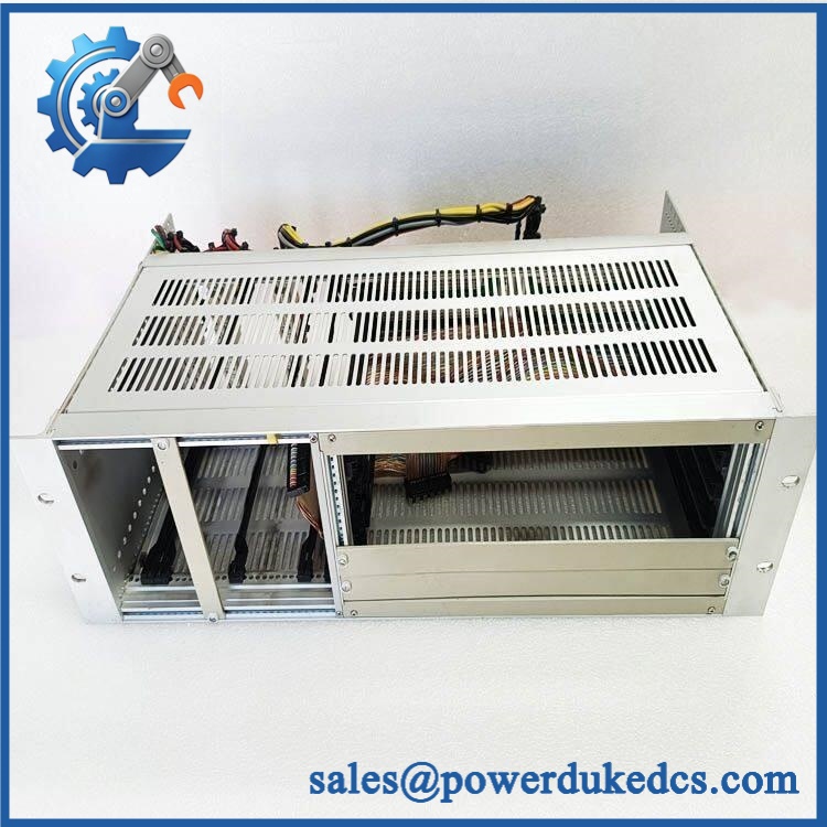
GE WESCOM D200 VME
Quality Assurance SOP
For New Surplus GE WESCOM VME hardware, the pre-shipment procedure should include:
- OEM anti-counterfeit visual inspection — inspect GE identification markings, board labels, PCB construction, connectors, revision codes, and component layout.
- Physical-condition inspection — examine VME edge connectors, mounting hardware, PCB surfaces, solder joints, capacitors, and exposed components for corrosion or mechanical damage.
- Part-number and revision verification — record every visible identification code before testing and compare it with the customer’s requested hardware.
- Power-on self-test (POST) — install the unit in a compatible test environment and verify normal power-up behavior and available ERR/RUN or diagnostic indicators.
- VME bus verification — confirm that the tested module communicates correctly across a compatible VME backplane.
- Processor and memory verification — where applicable, verify processor initialization, memory recognition, and normal boot behavior.
- Communication handshake verification — test supported communication paths with compatible control hardware or a qualified test fixture.
- I/O verification — for I/O hardware, validate representative channels against the applicable hardware specification and test procedure.
- Configuration record — photograph the nameplate, revision markings, connectors, and test results for the shipment file.
- ESD-controlled packing — protect the VME connector and PCB using ESD-safe packaging and appropriate mechanical cushioning.
Field note: because “WESCOM VME” identifies a system family rather than one unambiguous board-level part number, the exact module number should be confirmed before treating the item as a drop-in replacement.











 Start Chat


