

Description
- Brand: Pepperl+Fuchs
- Full Model Number: KFD2-VR4-Ex1.26
- System/Series Family: K-System Intrinsic Safety Isolated Barrier
- Core Function: Single-channel voltage repeater providing isolated power and signal transfer for hazardous-area vibration sensors or accelerometers
- Top 3 Hardcore Specs: 0 to -20 V voltage input/output; 24 V DC supply, 19–30 V DC operating range; SIL 2 according to IEC/EN 61508
- Field Sensor Supply: 3.6 mA / 5.3 mA / 8.9 mA for selected 2-wire sensors; 18 V at 20 mA for 3-wire sensors
- Isolation: Galvanically isolated input/output and input/power supply
- Dimensions: 20 mm W × 119 mm H × 115 mm D
- Weight: Approx. 160 g
- Mounting: DIN rail
- Stock Status: Availability to be confirmed by batch; New Surplus or Fully Tested Refurbished
Module 3: Technical Product Introduction
The KFD2-VR4-Ex1.26 addresses a very specific instrumentation problem: transferring a vibration-sensor voltage signal from a hazardous area into a safe control system while supplying the sensor through an intrinsic-safety interface. Although the supplied listing identifies the unit as HIMA, manufacturer documentation identifies KFD2-VR4-Ex1.26 as a Pepperl+Fuchs product. It is a one-channel K-System isolated barrier with 0 to -20 V input and output, intended for vibration sensors such as Bently Nevada devices or accelerometers.
Electrical details matter here. Depending on the terminal arrangement, the unit provides 3.6 mA, 5.3 mA, or 8.9 mA for specified 2-wire sensors, or 18 V at 20 mA for a 3-wire sensor. Its supply range is 19–30 V DC, with no more than 1.6 W power consumption and approximately 1.2 W dissipation. The published functional-safety documentation rates the device up to SIL 2 under its stated conditions.
Module 4: Application Scenarios & Field Realities
- When monitoring rotating equipment inside a hazardous area, the KFD2-VR4-Ex1.26 can sit between the field vibration sensor and the non-hazardous monitoring system, providing both the sensor supply path and isolated voltage transfer. That architecture is particularly relevant to machinery protection and condition-monitoring circuits where direct field-side wiring is restricted.
- For Bently Nevada-type vibration instrumentation, the terminal configuration must match the actual sensor arrangement. The unit supports several sensor supply currents for 2-wire devices and a separate 3-wire mode with 18 V at 20 mA; selecting the wrong wiring scheme can produce an apparently healthy interface with an invalid field signal.
- Inside a compact marshalling cabinet, the 20 mm width and DIN-rail construction are useful when cabinet space is already tight. The device is powered through terminals 11+ and 12- or through the Power Rail arrangement, depending on the installation architecture.
- Where functional-safety documentation is part of the project file, do not treat this as an ordinary signal converter. Pepperl+Fuchs publishes a dedicated functional-safety manual covering the device, its safety-related interfaces, assumptions, safe-state behavior, and SIL-related parameters.
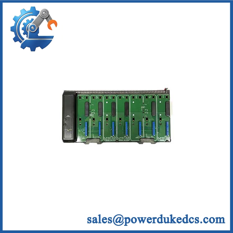
Pepperl+Fuchs KFD2-VR4-Ex1.26
Module 5: Migration, Compatibility & Installation Traps
Replacement Matrix
Replacement classification: Drop-in Replacement only for the same KFD2-VR4-Ex1.26 device when the terminal arrangement, sensor type, hazardous-area design, power architecture, and project documentation are unchanged.
Software compatibility: Hardware interface device — no application software update is normally associated with the repeater itself. The downstream PLC, vibration monitor, or protection system still needs verification for input scaling and signal limits.
Cross-model replacement: Not automatically interchangeable. A different isolated barrier may use another input range, sensor-current scheme, terminal assignment, certification basis, or safety rating. The 0 to -20 V signal range and sensor supply characteristics must match before substitution.
Field Traps — Watch Out
1. Terminal configuration is the first trap. The KFD2-VR4-Ex1.26 uses multiple field terminals to select the applicable sensor supply arrangement. A wiring change made for another repeater model can alter the supplied sensor current or produce an incorrect signal path. Verify the device wiring diagram against the actual sensor datasheet before applying power.
2. Do not assume any negative-voltage signal is interchangeable. This unit is specifically specified for a 0 to -20 V input and output. If the existing monitoring circuit expects 0 to +10 V, 4-20 mA, or a different dynamic range, the -Ex1.26 is not a like-for-like electrical substitute without additional interface hardware.
3. Ex parameters remain part of the installation calculation. The published approval data includes intrinsic-safety parameters such as Uo, Io, and Po. The complete field circuit—including the sensor, cable, and associated apparatus—must satisfy the applicable hazardous-area rules and certificate conditions.
Module 6: Quality Assurance SOP
Pre-Shipment Inspection Protocol for -Ex1.26
- OEM identity inspection: Confirm Pepperl+Fuchs manufacturer marking, exact -Ex1.26 designation, product labeling, terminal layout, and identification markings against manufacturer documentation.
- Mechanical inspection: Check the 20 mm housing, DIN-rail mounting interface, terminal blocks, retaining features, labels, and enclosure for cracks, deformation, corrosion, or unauthorized modification.
- Certification review: Verify applicable Ex and functional-safety markings against the intended application. Manufacturer documentation lists intrinsic-safety approvals and SIL 2 functional-safety capability.
- Power-input inspection: Verify the intended 24 V DC test supply and confirm operation across the published 19–30 V DC range where the laboratory test procedure permits it.
- Power-on verification: Energize under controlled conditions and check the green power indication, current consumption, abnormal heating, and visible fault conditions.
- Signal-path test: Apply representative 0 to -20 V input signals and verify corresponding isolated output behavior across the specified operating range.
- Sensor-supply verification: Test the applicable 2-wire or 3-wire configuration and verify the expected supply current or 18 V / 20 mA operating point against the selected wiring mode.
- Isolation verification: Check the relevant input/output and input/power isolation characteristics with appropriate laboratory instruments and procedures.
- Functional-safety documentation check: Compare the recorded test configuration with the applicable Pepperl+Fuchs functional-safety documentation before release.
- Final QC record: Record model, identification data, test date, measured values, test configuration, inspector approval, and packaging condition.
- ESD and mechanical protection: Protect the unit against electrostatic discharge, terminal damage, shock, moisture, and contamination during final packing and shipment.



 Start Chat


