

Description
- Brand HIMA / Pepperl+Fuchs K-System
- Full Model Number KFD2-STC4-Ex1
- System/Series Family Pepperl+Fuchs K-System
- Core Function 1-channel isolated SMART transmitter power supply and signal conditioner for hazardous-area 0/4–20 mA instrumentation
- Top 3 Hardcore Specs 20–35 VDC supply | 0/4–20 mA input/output | SIL 2 IEC/EN 61508
- Stock Status New Surplus — confirm physical condition and availability before order
Module 3: Technical Product Introduction
When a hazardous-area transmitter must interface with a control system without sacrificing loop isolation, the KFD2-STC4-Ex1 provides the required interface in a compact single-channel format. The unit is a SMART transmitter power supply with galvanic isolation, accepting 2-wire and 3-wire SMART transmitters as well as 2-wire current sources and reproducing a 0/4–20 mA signal on the control side. Pepperl+Fuchs specifies Power Rail or terminal-based 24 VDC supply, with an allowable supply range of 20–35 VDC.
Signal timing is also worth checking during a replacement. The specified settling time is 200 µs, while rise and fall time are 20 µs; output load capability reaches 800 Ω at 20 mA. At 20 °C, total signal deviation is specified at no more than 10 µA, including calibration, linearity, hysteresis, load, and supply-voltage effects. The module also carries SIL 2 functional-safety capability and hazardous-area certifications, making exact part-number matching important during MRO replacement.
Module 4: Application Scenarios & Field Realities
- On refinery or chemical-plant transmitter loops, the KFD2-STC4-Ex1 is appropriate where a field transmitter is installed on the hazardous side and the DCS or PLC receives a conditioned 4–20 mA signal on the safe side. The barrier supplies the field device while maintaining electrical isolation between the two sides.
- For SMART instrumentation using 2-wire or 3-wire transmitters, the input arrangement supports both transmitter types as well as 2-wire SMART current sources. During a shutdown replacement, terminal identification should be checked against the actual field wiring rather than copied from a visually similar barrier.
- Where long control-side cable runs are present, the specified output load of up to 800 Ω at 20 mA provides useful loop margin, but the actual loop resistance still needs to be calculated. Cable resistance, intrinsically safe interfaces, and receiver input resistance all consume that allowance.
- In safety-related instrumentation architectures, the SIL 2 capability can be relevant when the module is incorporated into a properly designed safety function. Certification of the barrier alone does not make the complete loop SIL 2; the transmitter, logic solver, wiring, diagnostics, and proof-test assumptions must all satisfy the applicable safety design.
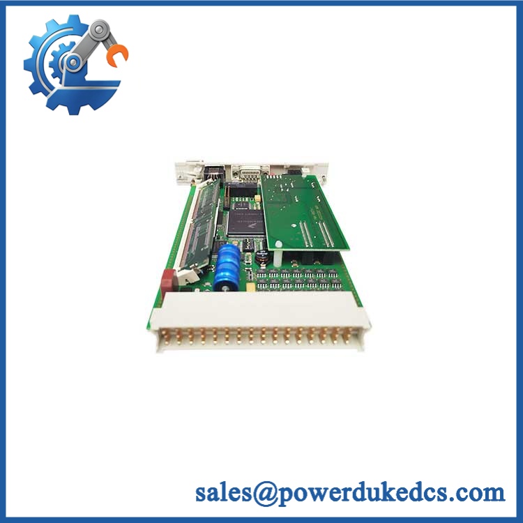
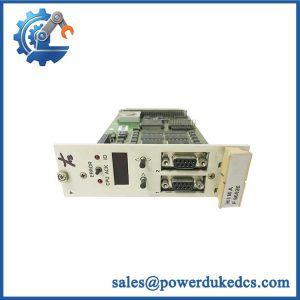
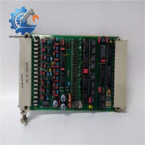
HIMA KFD2-STC4-Ex1
Module 5: Migration, Compatibility & Installation Traps
Replacement Matrix
| Replacement Status | Engineering Assessment |
|---|---|
| Drop-in Replacement | Yes, for an existing KFD2-STC4-Ex1 installation using the same terminal arrangement, hazardous-area concept, and approved system design. |
| Software Compatible | Yes. This is an analog isolation/power interface rather than a programmable controller module, so no firmware download or application recompilation is normally associated with a like-for-like replacement. |
| Hardware Modification Required | Normally no for a true part-number replacement. Changes may be required when migrating from a different barrier family, wiring topology, certification arrangement, or receiver load specification. |
⚠️ Field Traps: Watch Out
Do not substitute by current range alone. The KFD2-STC4-Ex1 is not simply a generic 4–20 mA isolator. It provides transmitter excitation as well as signal conditioning, and its hazardous-area parameters must match the field device and installation concept. Pepperl+Fuchs specifies different terminal combinations for the supported input arrangements.
Verify hazardous-area documentation before energizing the loop. The published data includes ATEX and IECEx-related parameters such as maximum safe voltage, output energy limits, and intrinsic-safety characteristics. These values are part of the approved installation, not optional wiring details.
Check receiver loading. The standard KFD2-STC4-Ex1 is specified for an output load of 0–800 Ω at 20 mA. A replacement may appear to function at low current while becoming inaccurate when the loop approaches its resistance limit.
Module 6: Quality Assurance SOP
Every surplus -Ex1 should be treated as an instrumentation component requiring electrical verification, not merely a visual stock check.
- OEM anti-counterfeit visual inspection: Verify the Pepperl+Fuchs identification, exact -Ex1 designation, enclosure geometry, terminal layout, front labeling, and visible product markings against OEM references.
- Part-number and traceability check: Record the complete model designation and available serial or manufacturing information before testing.
- Mechanical inspection: Examine the 35 mm DIN-rail mounting interface, screw terminals, enclosure, labeling area, and connector condition for damage or unauthorized modification.
- Power-input verification: Apply a controlled DC supply within the specified 20–35 VDC range and confirm normal module operation and supply current behavior.
- Transmitter excitation test: Confirm that the field-side circuit provides the specified transmitter supply conditions under controlled loop-test conditions.
- 0/4–20 mA transfer test: Inject calibrated analog current and verify proportional control-side output across representative points, including low-scale, mid-scale, and full-scale conditions.
- Load test: Verify output behavior under an appropriate simulated loop burden, taking the 800 Ω maximum load specification into account.
- Isolation verification: Check the electrical separation between field-side input, control-side output, and supply connections according to the applicable test procedure and certification requirements.
- Response verification: Confirm signal response against the documented 200 µs settling time and 20 µs rise/fall characteristics where the test fixture supports dynamic measurement.
- Indicator inspection: Check the front LED or status indication for expected behavior during power-up and analog-loop testing.
- Communication handshake verification: Not applicable as a digital communication device. Instead, perform a control-loop acceptance check through the connected analog input channel to confirm correct 0/4–20 mA transfer.
- Final QC record: Document measured supply voltage, input current, output current, load condition, isolation result, visual inspection, and traceability information before packaging.
Important identification note: The supplied inventory label lists HIMA, while -Ex1 is documented by Pepperl+Fuchs as a K-System SMART Transmitter Power Supply. For procurement, replacement, certification, and technical documentation, the exact manufacturer designation should therefore be confirmed against the physical unit and project BOM before shipment.



 Start Chat


