

Description
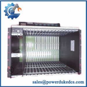
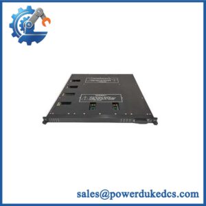
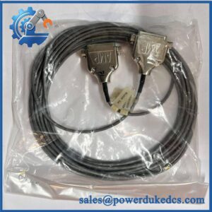
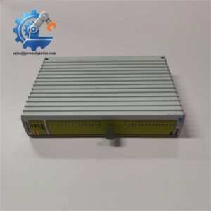
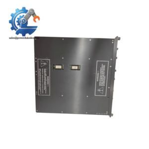
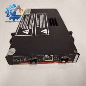
Unboxing & Physical Snapshot
- Manufacturer: TRICONEX / Invensys
- Part Number: 3000110-360
- Product type: Tricon field termination/baseplate assembly for 24 VDC digital inputs.
- Function: Provides the physical termination interface for supported Tricon digital-input modules and external terminators.
- Application: Commoned 24 VDC digital-input field termination.
- Associated module family: Documentation associates 3000110-360 with commoned 24 VDC digital-input configurations, including 3503E.
- Approximate physical dimensions: One supplier lists 17.8 × 17.8 × 2.5 cm; use the OEM mechanical drawing for cabinet engineering.
- Estimated shipping weight: Approximately 0.3 kg for the baseplate according to one supplier; another listing gives 7 lb, so the actual packed unit should be weighed before freight documentation.
- What’s in the box: 3000110-360 baseplate/termination assembly and mounting hardware only where specifically included in the purchase order.
- Physical inspection: Check terminal positions, mounting holes, connector/interface points, insulating surfaces, and the part-number label.
Product Introduction
The TRICONEX 3000110-360 is a field-termination component used within the Tricon I/O architecture. Its job is physical rather than computational: it provides the connection point between the field wiring and the applicable Tricon digital-input interface. A Tricon v9–v10 field-termination guide identifies 3000110-360 for 24 VDC, commoned digital-input arrangements.
This distinction matters during spare-parts control. The part is not the active digital-input electronics itself. Commercial references also describe it as a baseplate for external terminators, with one catalog specifically identifying use with external terminators. Keep the baseplate, associated terminator, cable/interconnect hardware, and active I/O module as separate inventory identities unless the OEM documentation defines them as one assembly.
Core Technical Specifications
| Parameter | Value |
|---|---|
| Manufacturer | TRICONEX / Invensys |
| Part Number | 3000110-360 |
| Product Type | Digital Input Field-Termination/Baseplate Assembly |
| System | Tricon |
| Field Signal | Digital Input |
| Nominal Field Voltage | 24 VDC |
| Input Arrangement | Commoned |
| Associated DI Configuration | 3503E |
| Function | Field termination / external terminator interface |
| Mounting | Tricon field-termination architecture |
| Approx. Dimensions | 17.8 × 17.8 × 2.5 cm, supplier reference |
| Approx. Baseplate Weight | 0.3 kg, supplier reference |
| Firmware | None expected in the passive baseplate |
| Power Dissipation | Not applicable as an active processor/I/O module |
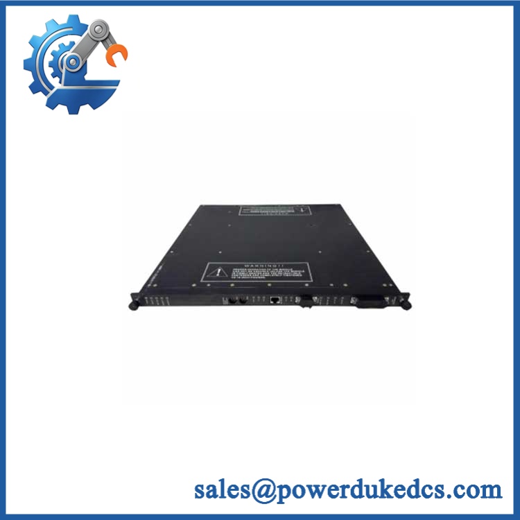
TRICONEX 3000110-360
The Tricon field-termination documentation specifically lists 3000110-360 for 24 VDC commoned digital-input configurations.
Do not apply the electrical specifications of the associated 3503E module directly to the 3000110-360. The baseplate establishes the physical termination architecture; the active I/O module determines the signal-processing characteristics.
? Global Compliance & Industry Certifications
The 3000110-360 should be evaluated as part of the complete Tricon safety-system installation.
- CE Mark: Verify the applicable Triconex conformity documentation for the exact assembly and system revision.
- UL/cUL: Confirm certification for the applicable Tricon chassis and field-termination configuration.
- ATEX/IECEx: Do not assume the baseplate itself is independently certified for hazardous-area installation. Verify the complete certified system and field interface.
- Marine approvals: DNV or equivalent approval must be confirmed for the exact Tricon configuration if used in marine service.
- Functional safety: The baseplate is an infrastructure component; it does not independently establish SIL compliance.
- EMC: Final performance depends on the complete installation, including shield termination, grounding, field wiring, cabinet construction, and associated Tricon modules.
The distinction between a passive termination assembly and active safety electronics is important for compliance records. Certification should follow the documented Tricon system architecture rather than being inferred from the part number alone.
Verify specific lot certifications with OEM.
? Long-Term Storage & Asset Preservation Guide
Keep the 3000110-360 clean and dry. Its primary storage risks are connector contamination, corrosion, damaged terminal hardware, and deformation of the insulating structure rather than firmware degradation.
Maintain warehouse humidity below 60% RH where practical. Avoid condensation and corrosive atmospheres, particularly around process plants where sulfur compounds, chlorine, or salt-laden air may be present.
Protect the terminal/interface surfaces from impact. Keep the assembly in its original packaging or an appropriate protective bag, and do not stack heavy modules on top of it (a bent mounting surface can prevent proper alignment with the associated termination hardware).
Before release, inspect the terminal interface, mounting holes, retaining hardware, insulation, and part-number label. Replace missing hardware before issuing the spare to the maintenance team.
Physical Installation Prerequisites
- Install the 3000110-360 only in the specified Tricon field-termination architecture.
- Verify that the intended application is 24 VDC commoned digital input.
- Confirm the associated Tricon I/O module and external termination arrangement before wiring.
- Verify terminal assignments against the approved Tricon field-termination drawing.
- Do not modify terminal wiring to accommodate a different voltage or input architecture.
- Maintain protective-earth and shield connections according to the approved system design.
- Keep digital-input wiring separated from high-energy AC, motor, and VFD wiring where required.
- Protect the terminal assembly from excessive mechanical cable strain.
- Maintain cabinet ventilation around adjacent active Tricon electronics.
- As a preliminary cabinet practice, preserve approximately 50 mm around ventilation paths, unless the applicable OEM installation drawing specifies another clearance.
- Perform point-to-point continuity and polarity checks before energizing the field circuits.
- After installation, verify the associated Tricon input module diagnostics and all affected field points.
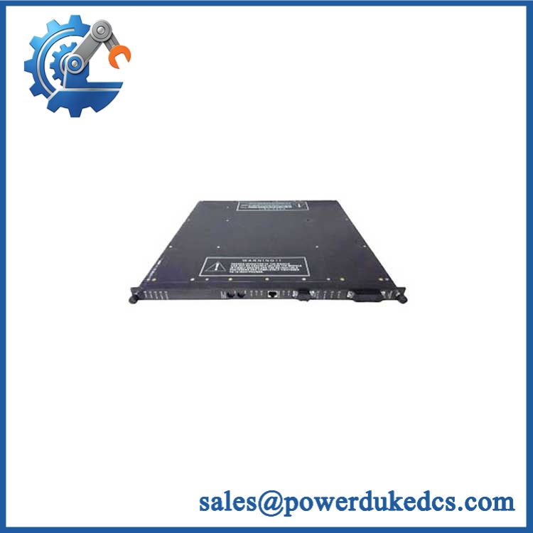
TRICONEX 3000110-360
Buyer’s FAQ
Which HS tariff code should be used for 3000110-360?
Do not automatically classify this part as an electronic input module. It is documented as a field-termination/baseplate component, so the correct HS classification should reflect its actual construction and function. Have the customs broker validate the destination-country tariff code before shipment.
What should I declare as Country of Origin?
Use the COO supported by the actual part and manufacturer/supplier traceability records. Do not infer origin from the seller’s warehouse or export location.
Does this part require shipping insurance?
For a critical Tricon spare, insurance is reasonable. The baseplate itself is relatively simple, but damage to the mounting surface, terminal interface, or insulating components can make an otherwise scarce spare unusable.
Does 3000110-360 include the latest firmware?
No firmware should be expected. The 3000110-360 is a field-termination/baseplate component rather than a programmable Tricon processor or active I/O firmware device.
Asset-control recommendation
Record the item as:
TRICONEX 3000110-360 — 24 VDC COMMONED DIGITAL INPUT FIELD TERMINATION BASEPLATE
Do not merge it with 3000110-380, 3000120-360, or 3000120-380. The Tricon field-termination documentation assigns these part numbers to different signal types and configurations.



 Start Chat


