

Description
-
- Model: GE 869-E-P1-P1-B1-H-S-S-A-L-A-M-M-P-F-B-SE-N-N-B-N-1
- Brand: GE Multilin
- Series: Multilin 869 Motor Protection System
- Part Type: Drawout digital motor protection and management relay
- Core Function: Protects and monitors medium- and large-size induction and synchronous motors through current, voltage, thermal, frequency, ground-fault, startup, and breaker-related functions.
- Configuration: P1/P1 phase-current inputs use 1 A CT secondaries; B1 provides the configured ground-current/CBCT arrangement; H identifies the high-range control-power option. The remaining suffix fields define the ordered I/O, protection, communications, recording, and other feature configuration.
- Key Specifications: 1 A CT inputs, high-range control power, drawout construction, RS485 communications, Ethernet options, event recording, disturbance recording, motor thermal modeling, and configurable protection logic.
Product Introduction
A large motor can remain energized while its internal thermal condition, phase balance, or mechanical load moves toward a trip condition. The GE Multilin 869 is designed to combine these measurements with protection and management functions in one relay, reducing dependence on separate monitoring instruments for many motor-protection tasks.
Installed in a switchgear or motor-control lineup, the 869 supports medium- and large-size induction and synchronous motors. The supplied configuration uses 1 A phase CT inputs, a B1 ground-current arrangement, and the H high-voltage control-power range. Its drawout construction also makes the relay suitable for maintenance strategies where the case and field wiring remain installed while the relay body is removed under an approved procedure. The platform includes extensive event and disturbance recording, which is valuable during legacy-system maintenance and long-term asset preservation.
Core Technical Specifications
Parameter Value Manufacturer GE Multilin Product Family Multilin 8 Series Exact Order Code 869-E-P1-P1-B1-H-S-S-A-L-A-M-M-P-F-B-SE-N-N-B-N-1 Product Type Motor Protection System Application Medium and large induction and synchronous motors Mechanical Construction Drawout Language English Phase CT Input, Bank J P1 — 1 A three-phase current input Phase CT Input, Bank K P1 — 1 A three-phase current input Ground Current Option B1 — 1 A ground input with CBCT arrangement Control Power H — high-range configuration DC Supply 88–300 VDC operating range; 125–250 VDC nominal range AC Supply 88–265 VAC operating range; 100–240 VAC nominal range VT Input Range Approximately 10–260 V direct measurement range Frequency Measurement 3–72 Hz Phase CT Primary Setting Range 1–12,000 A Phase CT Secondary 1 A Digital Inputs Six or more, depending on ordered I/O configuration Digital Input Type Wet or dry contact, configuration-dependent Digital Input Thresholds Selectable thresholds based on hardware configuration RTD Support 3-wire 100 Ω platinum when the RTD option is installed RTD Range Approximately -40°C to +250°C RS485 Isolated serial interface RS485 Baud Rate Up to 115.2 kbps RS485 Maximum Distance Up to 1,200 m / 4,000 ft under specified conditions Ethernet 10/100 Mbps, option-dependent USB USB service interface Event Recorder Up to 1,024 events Event Timestamp Resolution Up to 1 µs Motor Start Records Up to 6 records, 60 seconds each Transient Recorder Up to 16 analog and 32 digital channels Recorder Sampling Up to 128 samples per cycle Operating Temperature -40°C to +60°C Storage / Shipping Temperature -40°C to +85°C Humidity Up to 95% RH, non-condensing Maximum Altitude 2,000 m Pollution Degree II Overvoltage Category III Approx. Weight 9 kg / 20 lb Mounting Panel-mounted drawout case Power and Thermal Note
The H configuration uses a broad high-voltage auxiliary supply range. For engineering calculations, use the 125–250 VDC nominal range or 100–240 VAC nominal range and the actual relay configuration rather than a generic 24 V control-power assumption.
The approximately 9 kg chassis is substantially heavier than a conventional PLC I/O module, and cabinet thermal calculations should include the relay together with neighboring switchgear and protection equipment. A 50°C+ cabinet ambient is particularly relevant because the documented upper continuous operating limit is approximately 60°C.
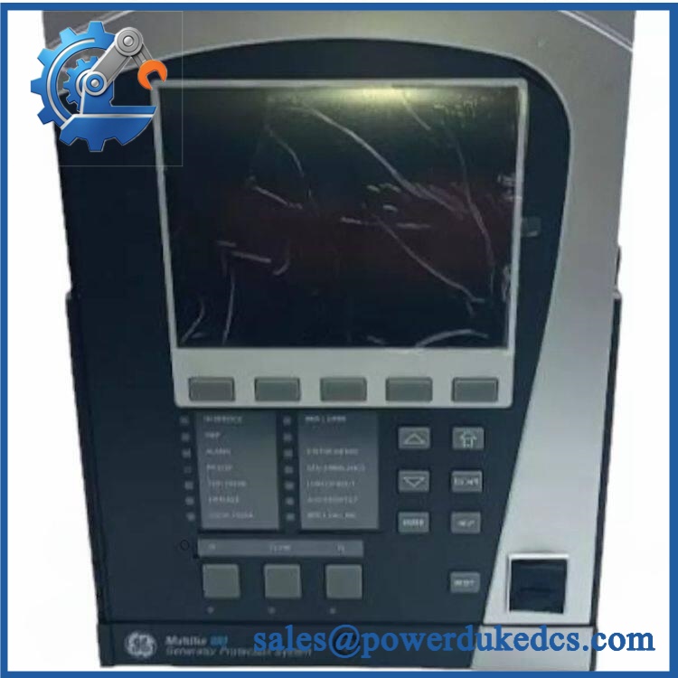
GE 869-E-P1-P1-B1-H-S-S-A-L-A-M-M-P-F-B-SE-N-N-B-N-1
Application Scenarios & Pain Points
In a compressor train, repeated acceleration trips can be difficult to distinguish from a genuine motor fault. The 869 includes motor-start supervision, thermal modeling, overcurrent, undercurrent, current-unbalance, stall, jam, voltage, and frequency protection functions, allowing the protection record to be correlated with the actual starting event.
For refinery and petrochemical motor feeders, the relay can monitor phase and ground current as well as voltage, frequency, power, power factor, and related electrical parameters. The P1 configuration is important here because it expects 1 A CT secondaries, not the 5 A secondary arrangement used by other 869 configurations.
Within large synchronous-motor applications, the platform supports functions related to excitation, loss of excitation, field conditions, power factor, and synchronous starting when the required options are fitted.
During DCS or SCADA integration, RS485 and Ethernet interfaces can provide relay data to higher-level systems. Network performance still depends on the selected communications hardware, protocol configuration, addressing, grounding, shielding, and topology.
In high-temperature motor-control rooms, the 869’s -40°C to +60°C operating range provides a defined boundary rather than unlimited environmental tolerance. Cabinet ventilation, door-mounted heat sources, adjacent protection relays, and dust accumulation should all be reviewed.
🚨 Common Error Codes & Diagnostic Symptoms
Symptom/Code:
Relay Not Ready→ Diagnosis: The relay has not reached its configured installation-ready state, commonly after initial configuration, maintenance, or a major settings change. This is a setup state and does not by itself prove hardware failure. → Action: Complete the required product setup and installation sequence, then verify the relay returns to service.Symptom/Code: Major self-test failure / red
IN SERVICEindication → Diagnosis: Internal diagnostics have identified a serious hardware or system condition that can inhibit protection and control functions. → Action: Capture the displayed diagnostic or target message, isolate external wiring causes, and replace or service the relay when an internal fault is confirmed.Symptom/Code: Protection relay remains operational but SCADA communication is lost → Diagnosis: Check the Ethernet or RS485 path, addressing, termination, shield grounding, and protocol configuration before replacing the relay. Communications failure does not necessarily mean the protection processor has failed. → Action: Correct the communication path first; replace the relay only after the interface itself has been confirmed defective.
🚨 Cross-Reference & Lifecycle Migration
The 869 is a highly configurable protection platform. Its complete order code determines functions that can materially change the electrical and mechanical requirements.
For this configuration:
- E identifies the language selection.
- P1 identifies a 1 A three-phase current input for the first phase-current section.
- P1 identifies another 1 A three-phase current input section.
- B1 identifies the specified ground-current/CBCT arrangement.
- H identifies the high-range control-power option.
- The remaining positions must be interpreted against the applicable GE ordering-code revision before procurement.
A different 869 with a 5 A CT input, different ground-current option, different control power, enhanced communications, different I/O cards, or different environmental options should not be treated as a direct replacement merely because the front panel says “869.”
Cross-Reference and Migration
GE also provides 469-to-869 retrofit paths for legacy motor-protection installations. This can be useful for obsolescence planning, but a retrofit involves more than exchanging the relay body. CT/VT circuits, mounting hardware, wiring, communications, settings, logic, and commissioning procedures must all be reviewed.
Firmware
Firmware is relevant to 869 replacement management. The relay platform supports software updates, and firmware compatibility can affect available functions and communication behavior. Preserve the existing firmware revision and approved settings file before commissioning a replacement.
A newer firmware revision should not automatically be treated as a drop-in upgrade. Verify supported hardware options and the plant’s validated settings baseline first.
Lifecycle Status
Active / Current Platform. The Multilin 869 remains part of GE’s current motor-protection portfolio. That provides a different procurement profile from a discontinued relay family, although this specific configuration still requires exact option matching.
For buffer-stock planning, maintain a configuration-specific spare record rather than a generic “GE 869” entry.
Field Engineer’s Tech Notes
Warning 1 — Verify the 1 A CT configuration before connecting secondary circuits.
This relay is ordered with P1 phase-current inputs, so the intended CT secondary is 1 A. Never connect a 5 A CT circuit based only on the physical connector arrangement. Confirm the CT ratio and secondary rating from the switchgear drawings before energization.Warning 2 — Confirm the H control-power range before applying auxiliary voltage.
The H configuration belongs to the high-voltage supply family. Do not connect a 125 VDC or 120 VAC circuit to a relay whose actual nameplate specifies another supply range, and never assume another 869 in the same lineup has the same power option.Strict QA & Testing SOP
Step 1 — Nameplate verification
Record the full 869-E-P1-P1-B1-H-S-S-A-L-A-M-M-P-F-B-SE-N-N-B-N-1 ordering code, serial number, hardware revision, firmware revision, and certification markings.Step 2 — Mechanical inspection
Inspect the drawout handle, captive hardware, front display, keypad, LED indicators, rear terminal blocks, CT/VT connectors, and grounding connections.Step 3 — Option verification
Confirm the P1/P1 current-input configuration, B1 ground arrangement, H control power, and all remaining option fields against the approved plant configuration.Step 4 — Control-power test
Apply controlled auxiliary power within the documented H-range limits. Verify startup and record all self-test conditions.Step 5 — Interface test
Verify the front-panel display, keypad, LEDs, and status indications.Step 6 — CT secondary injection
Use a calibrated relay test system with 1 A secondary injection. Verify phase-current magnitude, phase relationship, and associated metering.Step 7 — Ground-current testing
Test the B1 ground-current arrangement using the approved injection method. Where the application uses a CBCT, verify polarity and scaling against the site drawing.Step 8 — VT and frequency testing
Apply controlled voltage inputs and verify voltage, frequency, phase sequence, and calculated electrical parameters.Step 9 — Protection testing
Test the enabled protection functions relevant to the actual configuration, including thermal overload, overcurrent, ground fault, current unbalance, undercurrent, voltage, frequency, jam, stall, and breaker-related functions as applicable.Step 10 — RTD testing
Where RTD hardware is fitted, use calibrated 100 Ω platinum 3-wire simulation and verify representative temperature points.Step 11 — Output contact testing
Verify Trip, Alarm, Auxiliary, Start Inhibit, Critical Failure, and other configured outputs. Record pickup and release behavior where applicable.Step 12 — Communications testing
Verify communications and the ordered Ethernet interface. Check addressing, protocol response, network stability, and termination.Step 13 — Event and disturbance-record validation
Confirm access to event records, motor-start records, learned data, and disturbance captures.Step 14 — Firmware and settings record
Capture firmware information and retain the validated settings/configuration file.Step 15 — Final packaging
Protect the drawout mechanism, front display, rear connectors, and exposed terminals. Use ESD-safe packaging with rigid cushioning.Test videos are available for qualifying inventory when pre-shipment inspection evidence is required.
Buyer’s FAQ
Q1. Can I hot-swap the GE 869?
The 869 has a drawout construction, but this does not constitute blanket authorization for energized withdrawal. CT circuits, VT circuits, trip wiring, auxiliary power, and switchgear interlocks must be handled according to the approved site procedure.
Never intentionally open an energized CT secondary.
Q2. How do I verify a New Original unit?
Check the complete ordering code on the physical nameplate. For this model, verify P1/P1 phase-current inputs, B1 ground configuration, H control power, and the remaining option positions.
For controlled procurement, request photographs of the actual relay, serial number, rear terminals, hardware revision, packaging, and available firmware information.
Q3. What warranty should be specified?
Warranty depends on whether the relay is supplied directly through an authorized channel or through a secondary-market supplier. For New Surplus or refurbished units, the seller’s warranty is a commercial condition and should not be treated as an OEM warranty.
Specify the exact inventory condition and warranty duration in the purchase order.
Q4. Does this relay include the latest firmware?
Not necessarily. The 869 platform supports firmware revisions, and different firmware levels can interact with hardware options and application configuration.
For replacement control, record the installed firmware before removal and compare it with the replacement unit. Preserve the approved settings file and verify communications and protection functions after any firmware change.
Asset-Control Note
The GE 869-E-P1-P1-B1-H-S-S-A-L-A-M-M-P-F-B-SE-N-N-B-N-1 is a configuration-specific Multilin 869 motor protection relay using 1 A phase CT inputs and the H high-range control-power option. Its current platform status makes long-term sourcing different from that of discontinued GE relay families, but exact option matching remains essential.
For warehouse records, retain the complete order code, serial number, hardware revision, firmware revision, CT/VT configuration, communications options, settings file, COO, certification evidence, QA results, and packaging condition as separate controlled fields.











 Start Chat


