

Description
- Model: ABB AIM0006
- Part Number: 2RCA021397A0001P
- Brand: ABB
- Series: ABB Relion 615/620 family
- Part Type: Analog Input Module
- Module Configuration: 5U + 4BI
- Core Function: Provides five voltage-measurement inputs together with four binary inputs for the host protection and control IED.
- Key Specs: Voltage inputs rated for 60–210 V, four binary inputs, connector X130 with 18 terminals, plug-in relay architecture, and compatibility with multiple Relion 615/620 applications.
Product Introduction
The AIM0006 is installed in the modular electronics section of ABB Relion protection and control relays, where it provides the voltage-measurement and binary-input portion of the IED’s signal interface. ABB installation documentation explicitly identifies AIM0006 as a “5U + 4BI” card variant, with four binary inputs and five voltage channels.
For an asset manager, the complete identification AIM0006 / 2RCA021397A0001P should stay together. ABB documentation shows AIM0006 installed at slot X130, while tested 615-series equipment records list the corresponding article number in the same slot. This is a relay-internal plug-in module, not a standalone PLC card, and its compatibility depends on the host Relion configuration (especially the voltage-input topology and binary-input arrangement).
Core Technical Specifications
| Parameter | Value |
|---|---|
| Manufacturer | ABB |
| Module Designation | AIM0006 |
| Article Number | 2RCA021397A0001P |
| Product Family | ABB Relion 615 / 620 |
| Module Type | Analog input module |
| Card Configuration | 5U + 4BI |
| Voltage Inputs | 5 |
| Binary Inputs | 4 |
| Voltage Input Range | 60–210 V |
| Reference Voltage Input | U_SYN / synchronization voltage input, depending on host configuration |
| Phase Voltage Inputs | U1, U2, U3 |
| Residual Voltage Input | Uo |
| Binary Input Channels | BI1–BI4 |
| Connector | X130 |
| Connector Positions | 18 terminals |
| Input Terminal Groups | 1–8 for BI; 9–18 for voltage inputs |
| Voltage Reference | N / neutral terminal arrangement as shown in ABB diagrams |
| Relay Architecture | Plug-in module |
| Typical Host Applications | REF615, RED615, REG615, RET615 and related Relion configurations |
| Firmware | Managed by host IED; no independent user firmware specification established |
| Module Width | Host-relay dependent |
| Module Weight | Exact OEM standalone weight not established |
| Lifecycle | Legacy Relion hardware |
ABB’s connection diagrams show X130 terminals 1–8 as four binary inputs and terminals 9–18 as five voltage-related channels: U12B/U_SYN, U1, U2, U3, and Uo, with the applicable configuration determining which voltage channels are used.
A KEMA test record for a Relion 615 device specifically lists , article number 2RCA021397A0001, at slot X130.
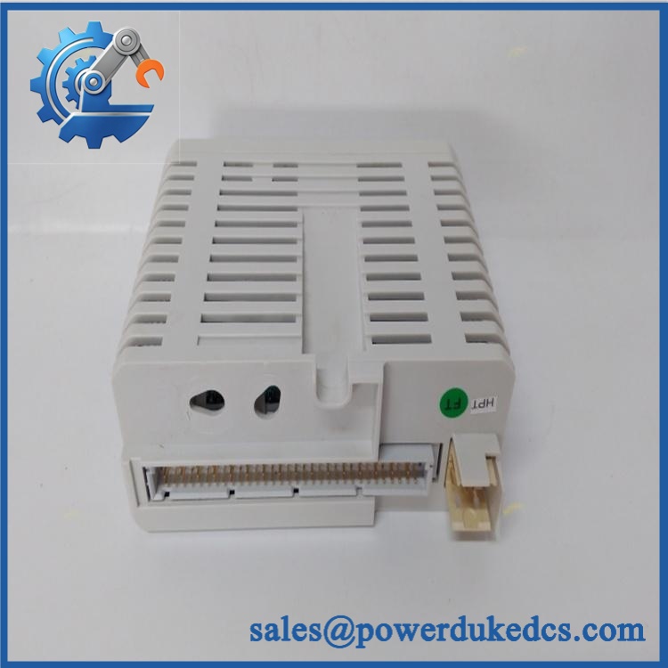
ABB AIM0006 2RCA021397A0001P
Application Scenarios & Pain Points
Micro-case — feeder protection: A REF615 or related Relion IED reports abnormal voltage measurements while the external VT wiring remains healthy. A module-level test can isolate the from the rest of the protection relay before a complete relay replacement is considered.
In substation feeder applications, the five-voltage-channel arrangement can provide phase and residual/synchronization voltage information required by the host protection configuration. ABB’s drawings show 60–210 V markings for these voltage inputs.
For transformer, generator, and line-protection applications, appears in different Relion 615/620 configuration drawings. The specific host relay determines how the five voltage inputs are assigned, so the module should be matched to the original configuration rather than ordered solely by the designation.
Where binary status signals are required, the same X130 module contributes four binary inputs. This can reduce the need for a separate input module within configurations designed around the arrangement.
At 50°C+ cabinet temperatures, temperature-controlled testing becomes useful before releasing a long-stored spare. The exact permitted ambient range comes from the complete host IED and enclosure specification, not from alone.
🚨 Common Error Codes & Diagnostic Symptoms
The documentation reviewed does not establish an independent universal numerical fault-code table. Diagnostics are normally presented through the host Relion IED.
Symptom/Code: Voltage channels read zero or implausible values → Diagnosis: Possible VT wiring fault, blown external fuse, connector problem, incorrect configuration, or failure within the voltage-input circuitry → Action: Verify the external VT circuit and connections first, then substitute a known-good if the fault follows the module.
Symptom/Code: One or more binary inputs remain fixed → Diagnosis: Check the external contact circuit, input common arrangement, terminal wiring, and configuration before identifying an internal module fault → Action: Simulate the binary input at and replace the module only when the channel fails controlled testing.
Symptom/Code: Multiple voltage and binary channels fail together → Diagnosis: A connector seating problem, host-module interface issue, or common IED fault is more likely than several independent channel failures → Action: Inspect and the plug-in interface, then test with a verified replacement module.
🚨 Cross-Reference & Lifecycle Migration
Exact Part Identity
The controlled identity should be:
ABB / 2RCA021397A0001P — 5U + 4BI Analog Input Module
ABB’s technical documentation identifies as the 5U + 4BI variant.
A KEMA-certified Relion 615 test configuration also lists an module with article number 2RCA021397A0001, installed at .
The supplied 2RCA021397A0001P should therefore be retained as the procurement identity. The trailing P should not be removed from purchasing records unless ABB documentation for the actual unit confirms equivalence.
Related Module Configurations
ABB documents AIM0003 as an alternative in certain configurations, with a different measurement arrangement. The application manuals explicitly describe versus AIM0003 (5U + 2RTD + 1 mA). These are functionally different module configurations and should not be treated as generic substitutes.
Firmware Requirement
itself is a plug-in acquisition module and does not have the same independent firmware-management model as the CPU or main application software of the host IED.
Firmware compatibility therefore needs to be evaluated at the complete Relion relay level. A replacement module should match the host’s hardware configuration, terminal arrangement, protection application, and validated product version.
Lifecycle Status
Lifecycle: Legacy / installed-base spare.
remains documented in ABB Relion 615/620 technical material, but the specific module belongs to an established protection-relay generation rather than a newly introduced product platform.
For critical substations, record the exact relay model, configuration code, article number, hardware revision, and installed software version together. A generic “” warehouse entry is not sufficiently precise.
Field Engineer’s Tech Notes
First warning: never move the module to a different Relion relay based only on connector fit. is used across multiple 615/620-family applications, but the voltage-channel assignment changes with the host configuration. Confirm the original terminal diagram before insertion.
Second warning: remember that the voltage inputs are not low-level analog inputs. ABB’s drawings identify 60–210 V connections at . Treat the VT secondary circuit accordingly and follow the relay’s isolation and electrical-safety procedure before disconnecting the plug-in unit.
Use ESD precautions when handling the module outside the relay chassis. Also photograph the wiring before removal.
Strict QA & Testing SOP
1. Inbound identity verification
Confirm and 2RCA021397A0001P on the physical unit. Record serial number, hardware revision, date code, labels, and packaging condition.
2. Physical inspection
Inspect the PCB assembly, connector interface, retaining features, terminal contacts, labels, and insulation barriers for contamination, corrosion, cracking, or mechanical damage.
3. Configuration verification
Confirm the module is the 5U + 4BI version. Compare the terminal arrangement with the customer’s original relay drawing.
4. Pre-power electrical inspection
Check the module and connector for abnormal continuity or signs of damage before applying voltage. Do not apply arbitrary test voltages to the field terminals.
5. Binary-input simulation
Use isolated test equipment to exercise BI1 through BI4 individually. Verify that the host IED detects each state change correctly.
6. Voltage-input simulation
Apply controlled, isolated voltage signals appropriate to the host relay’s approved test procedure. Verify U1, U2, U3, Uo, and the applicable synchronization-voltage input.
7. Measurement verification
Compare displayed voltage values, phase relationships, and residual-voltage calculations against calibrated test equipment.
8. Host-IED integration test
Install the module in a verified compatible Relion relay and confirm initialization, measurement acquisition, binary-input status, alarms, and protection functions dependent on the voltage channels.
9. Configuration retention check
Confirm the host relay retains the expected configuration after controlled power cycling. The module itself should not be treated as the repository for the host protection application.
10. Isolation and safety checks
Perform the applicable dielectric and insulation checks using the approved relay maintenance procedure. Protection-relay VT circuits require controlled test methods because the voltage terminals are not ordinary low-level signal inputs.
11. Extended observation
Monitor voltage stability, input transitions, connector integrity, and host-IED diagnostics during representative operation.
12. Final preservation
Place the approved module in ESD-safe packaging, protect the connector, retain the original identification labels, and attach the QC report.
Test videos are available when live-rig verification is performed and visual evidence is required for procurement approval.
Buyer’s FAQ
Is a GE module?
No. The exact identification / 2RCA021397A0001P is ABB. ABB documentation identifies as a Relion-series module.
What does “5U + 4BI” mean?
It denotes five voltage-input channels plus four binary inputs. ABB’s diagrams show four binary inputs on terminals 1–8 and five voltage-related circuits on terminals 9–18.
Can be hot-swapped?
Do not assume unrestricted live replacement. The module is part of a protection IED and its interface includes 60–210 V voltage circuits. Follow the specific Relion installation procedure and site switching/isolation requirements before removing the plug-in assembly.
How do I verify New Original authenticity and warranty?
Request photographs of the actual 2RCA021397A0001P, including the ABB identification label, article number, hardware revision, connector area, and original packaging. The purchasing document should state New Original, New Surplus, refurbished, or repaired condition, together with the test scope and warranty period.
For compliance and asset control, retain ABB + 2RCA021397A0001P + host Relion model + configuration + hardware revision + software version + COO + QC record + packaging condition in the same asset record.











 Start Chat


