

Description
Module 2: The 10-Second Procurement Snapshot
- Brand: ABB Bailey
- Full Model Number: IIMCP01
- Lifecycle Status: Legacy / Discontinued
- Core Function: Multibus communication processing for Bailey INFI 90 systems
- Top 3 Technical Specs: Port A and Port B interfaces; configurable baud rates; DIP-switch configuration
- Stock & Condition: New Surplus; tested inventory subject to physical stock confirmation; expedited dispatch available for confirmed stock
Module 3: Supply Chain & Technical Deep Dive
Legacy Bailey INFI 90 systems create a particular spare-parts problem: the communication processor may be small, but its failure can isolate controllers from the plant communication network. The IIMCP01 is a Multibus Communication Processor used in Bailey Net 90 and INFI 90 architectures. Available hardware documentation identifies the board with configurable communication ports, status LEDs, DIP switches, and connections to the IIMLM01 and CPU/terminal-server architecture.
For TCO, keeping one verified spare can be cheaper than waiting for a legacy replacement while a process unit remains unavailable. The IIMCP01 uses configurable serial communication characteristics, including selectable baud rates and parity settings. Documentation lists 9,600 and 19,200 baud configurations among the available settings, with additional switches for diagnostics, checksum, NVRAM, and RAM configuration. Do not copy generic specifications from unrelated IIMCP01 listings; configuration must be matched to the installed DCS.
Module 4: Migration, Compatibility & Field Traps
Replacement Matrix
| Replacement Category | Assessment |
|---|---|
| Drop-in Replacement | Yes, when replacing the same IIMCP01 configuration |
| Software Compatible | Configuration-dependent; verify communication parameters |
| Hardware Modification | Normally not required for an exact replacement |
| Engineering Approval | Recommended before installation |
⚠️ Field Trap 1: DIP-Switch Settings
The IIMCP01 is configured through board-mounted DIP switches. Documented settings include Port A and Port B parity, baud rate, diagnostic mode, firmware test mode, NVRAM, and RAM configuration.
Photograph every switch before removing the old board.
Do not assume factory-default settings match the plant configuration.
⚠️ Field Trap 2: Communication Parameters
A replacement can power up normally while communication remains down.
Check:
- Port A baud rate
- Port B baud rate
- Parity
- Stop-bit configuration
- Checksum setting
- Port B operating mode
- Diagnostic settings
- NVRAM configuration
One wrong DIP position can be enough to prevent expected communication.
⚠️ Field Trap 3: Installation Safety
ABB-related replacement documentation specifically warns about exposed AC and DC connections inside the cabinet and requires appropriate static-sensitive-device handling. The documented replacement procedure for the calls for removing workstation power before removing the module.
Power down according to the site isolation procedure. Use ESD protection.
Do not treat this as a simple board swap.
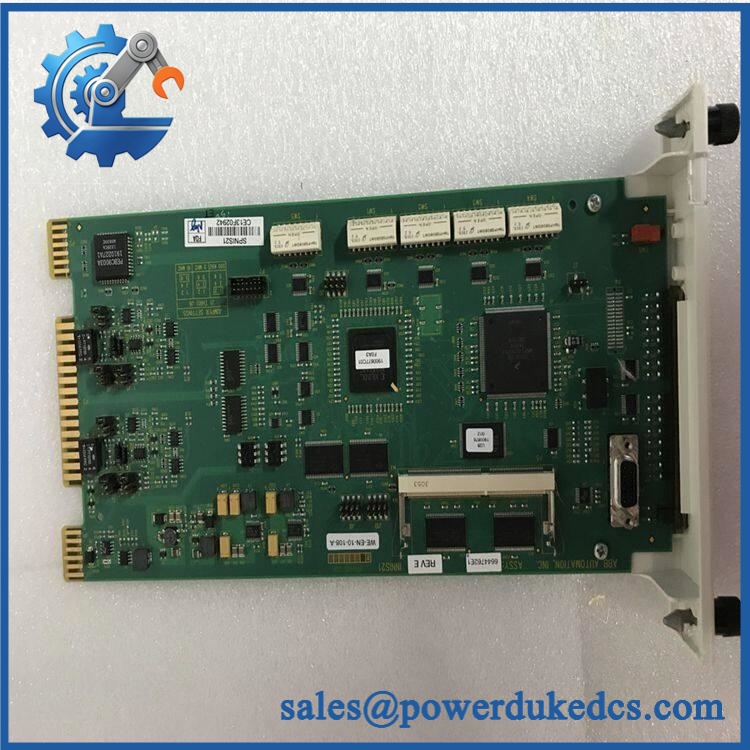
ABB IIMCP01
Module 5: Quality Assurance & Testing SOP
A legacy communication processor should pass both physical inspection and communication testing before shipment.
1. OEM Identification Check
- Verify ABB Bailey identification.
- Confirm marking.
- Record serial number where available.
- Photograph the nameplate and PCB.
- Check labels for alteration.
- Compare PCB layout with the specified module.
- Inspect original packaging where supplied.
2. Physical Inspection
Check the board for:
- Corrosion
- Oxidation
- Burn marks
- Cracked components
- Bent pins
- Damaged connectors
- Missing components
- Solder rework
- Contamination
- Mechanical damage
The edge connectors deserve close inspection because poor contact can create intermittent communication faults.
3. Power-On Self-Test
Using a compatible Bailey INFI 90 / Net 90 test environment:
- Install the board in the correct rack position.
- Apply the specified system power.
- Check module status LEDs.
- Verify startup behavior.
- Check diagnostic indications.
- Confirm module recognition.
- Record abnormal LED conditions.
4. Communication Testing
Where the appropriate test equipment is available:
- Verify Port A operation.
- Verify Port B operation.
- Test configured baud rate.
- Test parity configuration.
- Verify command-mode operation where applicable.
- Check communication stability.
- Verify interaction with the associated Multibus/INFI 90 equipment.
The available hardware manual identifies Port A and Port B configuration through SW0 and additional switch banks.
5. Configuration Verification
Before final QC:
- Photograph DIP-switch positions.
- Record jumper positions.
- Record baud-rate configuration.
- Record parity configuration.
- Record diagnostic settings.
- Compare settings against the customer’s original board where available.
6. Final QC
- Test Report completed
- Serial number recorded
- Communication results archived
- DIP-switch configuration photographed
- QC approval completed
- ESD packaging applied
- Protective cushioning installed
- Shipping carton sealed
Test photographs and available Test Reports can be supplied for procurement review.
Module 6: Procurement-Driven FAQ
1. Is the ABB actually in stock, and when can it ship?
Physical inventory should be confirmed against the exact model before the purchase order is released. For emergency DCS maintenance, confirm quantity, physical condition, destination, and dispatch cutoff in writing.
Legacy stock can change quickly.
2. How do you verify the condition of a surplus ?
The inspection covers the board identification, PCB condition, connectors, components, DIP switches, and signs of previous repair.
For tested inventory, request the serial-number record, inspection photographs, and Test Report. The documentation should correspond to the actual board being shipped.
3. What warranty and return terms should procurement require?
The quotation should clearly state the warranty period, covered functional failures, return authorization process, and inspection requirements.
For obsolete DCS hardware, a documented pre-shipment communication test provides a useful baseline for any subsequent warranty evaluation.
4. Are there firmware or configuration compatibility issues?
Configuration is the bigger concern.
The has configurable communication parameters and DIP-switch settings. Documentation identifies settings for baud rate, parity, checksum, diagnostics, NVRAM, and other operating functions.
Before replacement, save the old board’s switch configuration and verify it against the approved DCS configuration.
5. What information should I send for an urgent replacement quote?
Provide:
- model
- Clear nameplate photograph
- PCB photograph
- Existing DIP-switch settings
- Associated controller/rack information
- Communication configuration
- Quantity required
- Required delivery date
For this type of legacy communication processor, a clear photograph of the existing DIP switches is especially useful. It can reveal configuration differences before the replacement is approved.











 Start Chat


