

Description
Module 2: The 10-Second Procurement Snapshot
- Brand: ABB Bailey
- Full Model Number: IMDSI02
- Lifecycle Status: Legacy
- Core Function: 16-channel digital signal acquisition
- Product Type: Digital Slave Input Module
- Top 3 Technical Specs: 16 digital inputs; +5 VDC module supply; 24 VDC / 125 VDC / 120 VAC field input configurations
- System: Bailey INFI 90 Process Management System
- Mounting: One slot in Module Mounting Unit (MMU)
- Field Interface: P3 via termination unit or termination module
- Status Indication: 16 front-panel input LEDs
- Stock & Condition: New Surplus; physical stock confirmation required
The original ABB/Bailey manual confirms that IMDSI02 brings 16 separate digital signals into the INFI 90 system and occupies one MMU slot.
Module 3: Supply Chain & Technical Deep Dive
A failed digital input slave can remove field status signals from an operating INFI 90 DCS. That matters when those signals represent switches, contacts, solenoids, or other discrete process conditions. IMDSI02 provides the interface between these field inputs and the DCS processing layer, with the module communicating to a master through the slave expander bus.
From a TCO standpoint, this is a classic legacy-spare item: low physical size, but potentially high downtime exposure. The module provides 16 digital input channels and uses a +5 VDC internal supply; published documentation also identifies two groups of eight inputs and 16 front-panel status LEDs. Input configuration depends on the associated termination hardware, so procurement should confirm the installed TU/TM arrangement rather than relying only on the module number. ABB documentation identifies the field connection through connector P3 and a termination unit or termination module.
Module 4: Migration, Compatibility & Field Traps
Replacement Matrix
| Replacement Scenario | Assessment | Required Action |
|---|---|---|
| Same IMDSI02 module | Drop-in Replacement | Verify module identity and termination hardware |
| Same module with different revision | Software / Hardware Compatibility Check | Compare revision and system configuration |
| IMDSI12 or another digital-input family | Not automatically compatible | Check signal type, addressing, and termination |
| Different termination unit | Hardware Modification may be required | Verify wiring and jumper configuration |
⚠️ Field Traps: Watch Out
Termination-unit configuration: The field wiring does not terminate directly on the PCB. The IMDSI02 uses P3 to connect to a TU/TM, where the field wiring is physically connected. Verify the existing termination hardware before approving a replacement.
Input voltage configuration: Available documentation identifies support for different field-input configurations, including 24 VDC, 125 VDC, and 120 VAC. Do not assume the replacement configuration matches the removed module.
Input isolation: The manual describes 12 inputs as individually isolated, while two pairs share common positive input lines. This matters when checking field wiring and diagnosing unexpected signal interactions.
LED interpretation: Sixteen front-panel LEDs correspond to the individual inputs. Photograph the old module’s LED state before shutdown if the fault condition needs to be documented.
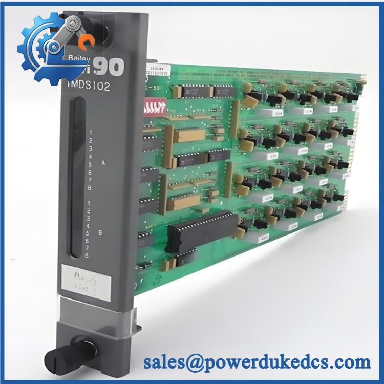
ABB IMDSI02
Module 5: Quality Assurance & Testing SOP
1. Incoming Inspection
- Verify ABB Bailey identification.
- Confirm IMDSI02 marking.
- Record serial and revision information.
- Inspect the PCB for corrosion or physical damage.
- Check card-edge connectors.
- Inspect mounting hardware and captive screws.
- Look for burn marks, cracked components, or previous repair evidence.
2. OEM Authenticity Inspection
- Check ABB/Bailey markings.
- Compare PCB layout against an approved reference.
- Verify connector positions.
- Inspect component and label consistency.
- Photograph the identification label.
- Record available traceability information.
3. Power-On Self-Test
Using a compatible INFI 90 test environment:
- Apply the specified +5 VDC supply.
- Check module startup.
- Verify available module status indications.
- Monitor supply current.
- Confirm that the module initializes correctly.
The published product information lists a +5 VDC supply requirement and approximately 80 mA module consumption.
4. Digital Input Testing
A suitable test fixture should verify all applicable channels:
- Test input channel 1 through 16.
- Apply the configured digital input signal.
- Confirm corresponding front-panel LED response.
- Verify status transmission through the slave expander bus.
- Test both input groups.
- Check applicable isolation behavior.
The original manual specifically describes 16 digital input status LEDs, with the channels divided into groups A and B.
5. Extended Functional Test
Where the correct INFI 90 rack is available:
- Run the module continuously.
- Exercise multiple input states.
- Monitor intermittent signal changes.
- Check communication with the master module.
- Record abnormal diagnostics.
- Document the test duration.
A Test Report should contain the model, serial number, revision, test rack, input configuration, test date, and channel-by-channel results.
6. Final QC & Packaging
- QC inspection signed.
- ESD-safe packaging applied.
- Card-edge contacts protected.
- Shock protection added.
- QC label attached.
- Test report retained with the inventory record.
Test photographs or video can be supplied when available.
Module 6: Procurement-Driven FAQ
1. Is ABB physically in stock, and what is the shipping cutoff?
Physical inventory should be confirmed against the actual unit before order release. For an urgent DCS requirement, request confirmation of the exact model, revision, condition, test status, quantity available, and dispatch cutoff.
2. How do you verify a surplus ?
Inspection should cover the PCB, card-edge connectors, ABB/Bailey markings, mounting hardware, and visible component condition. Where an INFI 90 test rack is available, all 16 digital input channels should be checked rather than testing only one channel. The original documentation confirms the 16-channel architecture.
3. What warranty should I request for this legacy DCS module?
Request a written warranty period and defective-unit procedure before the PO is released. The terms should identify the claim window, required failure evidence, return procedure, and replacement or refund conditions.
4. Could the termination unit cause compatibility problems?
Yes. The module relies on a TU/TM for field wiring, and the input configuration is tied to the termination arrangement. The module manual specifies P3 as the field-signal connection to the termination hardware.
5. Can I replace with another ABB digital input module?
Not automatically. is specifically a 16-input Digital Slave Input module for the INFI 90 architecture. Another digital-input module may have different channel characteristics, termination requirements, or system configuration. Verify the exact DCS BOM and wiring documentation before substitution.











 Start Chat


