

Description
- Brand: ABB
- Full Model Number: INSUM MCU2 IVU02
- Product Type: MCU2 Voltage Unit
- Lifecycle Status: Legacy INSUM motor-management hardware; replacement availability requires exact configuration verification
- Core Function in System: Three-phase voltage measurement and auxiliary power supply for INSUM MCU2 motor-control units
- Top 3 Hardcore Specs: Up to 690 V voltage measurement; three-phase measurement; 50/60 Hz system frequency
- Compatible System: ABB INSUM MCU2
- Measurement Architecture: Integrated three-phase voltage transformers and measurement electronics
- Mechanical Arrangement: Side-by-side voltage unit attached to the MCU2 mounting rail
- Connection to MCU2: Flat cable
- Protection Function: Supports voltage-dependent protection and monitoring functions
- Condition & Lead Time: New, refurbished, or tested replacement stock subject to compatibility verification; emergency dispatch based on confirmed inventory
ABB’s INSUM MCU documentation identifies the Voltage Unit (VU) as an option for . The unit contains three-phase voltage measurement transformers and associated electronics, and it also provides the second auxiliary-power supply path, UAUX2. ABB specifies voltage measurement up to 690 V with the voltage unit; higher system voltages require an external voltage transformer.
Module 3: Technical Intro & Downtime Impact
A failed voltage unit can leave an INSUM without valid three-phase voltage feedback, disabling or corrupting voltage-dependent protection and monitoring functions. ABB INSUM IVU02 is the voltage-unit assembly associated with the architecture. It contains the three-phase voltage transformers and measurement electronics, connects to the through a flat cable, and is installed alongside the on the drawer mounting rail. ABB also states that the voltage unit is specifically matched to its respective and should not be mixed with another .
For MTTR reduction, the most useful engineering figures are 690 V maximum direct voltage measurement, three-phase measurement, and 50/60 Hz operation. The parameter documentation allows nominal-voltage configuration up to 690 V without an external VT; with an external voltage transformer, the system can be configured for motor supplies from 0.6 to 12.0 kV by entering the appropriate primary and secondary values. —The IVU02 therefore should not be selected purely by physical fit; its voltage-transformation characteristics must match the associated and motor-starter application.
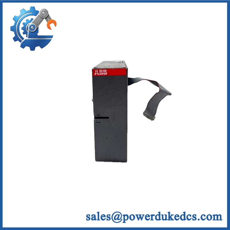
ABB INSUM MCU2 IVU02
Module 4: Dynamic Emergency Swap & Configuration Guide
1. Pre-Swap Prep — Freeze the motor-protection configuration
- Place the affected motor starter in the approved maintenance state.
- Isolate the starter and associated control power according to the site procedure.
- Verify absence of hazardous voltage before opening the drawer.
- Record INSUM IVU02 and the associated identification.
- Record the hardware/software revision and configured nominal motor voltage.
- Determine whether the system uses direct voltage measurement or an external VT.
- Record external VT primary and secondary values where applicable.
- Photograph the and IVU02 mounting arrangement, flat cable, and surrounding wiring.
- Back up or document the INSUM parameter set.
- Use ESD protection before handling the voltage unit.
ABB states that the voltage unit is an option for and that each voltage unit belongs to its respective and should not be mixed with another . This pairing requirement should be treated as a replacement control point.
2. Removal — Side-mounted voltage unit
- Confirm the motor-starter drawer is electrically safe.
- Identify the IVU02 flat-cable connection before disconnecting it.
- Disconnect the flat cable without stressing its contacts.
- Release the voltage unit from its drawer mounting arrangement.
- Remove the unit while supporting its housing to prevent cable or connector strain.
- Keep the removed separate from unrelated assemblies.
- Inspect the mounting rail, connector, flat cable, and interface for contamination, corrosion, bent contacts, or mechanical damage.
ABB’s MCU documentation describes the voltage unit as being installed side by side with the MCU main unit on the drawer mounting rail and connected to the baseplate through a flat cable.
3. Installation & Configuration — Match the voltage transformer characteristics
- Verify ABB INSUM before installation.
- Confirm the replacement is intended for the same hardware generation.
- Install the voltage unit in the original side-by-side position.
- Reconnect the flat cable correctly and fully.
- Verify the nominal-voltage setting.
- Where an external VT is used, verify External VT Installed = Yes.
- Confirm external VT primary and secondary values.
- Verify phase-voltage channel association and polarity.
- Check that the measured system voltage is within the direct-input range where no external VT is used.
- Restore the documented undervoltage and related voltage-dependent protection settings.
- Do not modify voltage scaling to compensate for an incorrectly selected voltage unit.
ABB’s parameter documentation states that voltage measurement can directly measure voltages up to 690 V. For higher-voltage applications, an external VT is required, with configurable primary and secondary values.
4. Power-On Self-Test (POST) — Prove three-phase voltage measurement
- Restore auxiliary/control power according to the INSUM procedure.
- Confirm the recognizes the installed voltage unit.
- Check for persistent voltage-measurement or device diagnostics.
- Verify all three phase-voltage measurements.
- Compare displayed values with calibrated field measurements.
- Confirm phase sequence and polarity.
- Verify the configured nominal voltage.
- Test undervoltage monitoring where enabled.
- Verify voltage-dependent starter logic and protection.
- Where an external VT is installed, confirm the displayed voltage corresponds correctly to the programmed VT ratio.
- Confirm the motor starter returns to the expected operational state before releasing it to service.
The voltage unit uses internal code signaling for automatic voltage-unit detection, according to ABB’s hardware documentation. This allows the to identify the connected voltage-unit configuration during startup.
Module 5: Quality Assurance & Testing SOP
The should be tested together with a compatible because voltage scaling is dependent on the paired motor-control configuration. Testing the voltage unit as an isolated generic board is insufficient.
1. OEM identity verification
- Verify ABB
- Verify
- Verify
- Confirm the voltage-unit hardware generation
- Compare housing, connector arrangement, labels, and mechanical geometry
- Perform OEM anti-counterfeit visual inspection
- Photograph all identification markings
2. Physical inspection
- Inspect the enclosure for cracks, deformation, contamination, and impact damage
- Check the flat-cable connector
- Inspect the voltage-input interface and insulation barriers
- Check mounting hardware
- Look for heat discoloration, tracking, or evidence of electrical overstress
- Inspect cable and connector locking features
3. Electrical screening
- Verify applicable auxiliary-supply paths according to the test procedure
- Check the flat-cable interface for continuity where appropriate
- Verify phase-input circuit integrity
- Check insulation condition using only the approved test method
- Do not apply arbitrary hipot voltages to the populated voltage-measurement electronics or transformer interfaces
4. Functional testing
- Install the on a compatible test assembly
- Perform power-on self-test
- Confirm automatic voltage-unit detection
- Apply balanced three-phase test voltage
- Verify all three measured phase voltages
- Check measurement scaling
- Verify phase sequence and polarity
- Perform voltage tests across the approved operating range
- Validate nominal-voltage configuration
- Test undervoltage alarm and trip functions where configured
- Test external-VT scaling where the application uses an external transformer
- Perform I/O full-range simulation for related functions where supported by the test fixture
- Record applied voltage, displayed voltage, scaling ratio, deviation, phase information, and final result
ABB’s parameter documentation provides a direct voltage range up to 690 V and external-VT configuration up to 12.0 kV primary voltage through programmed transformer ratios. Those values should form part of the acceptance test where applicable.
5. Final QC release
- Independent QC sign-off
- pairing compatibility documented
- ESD-safe packaging
- Flat-cable connector protection
- Final identification check of INSUM
- Retain voltage calibration/test records
- Retain inspection photographs
- Release only after three-phase measurement verification passes
Module 6: Maintenance & Reliability FAQ
Q1. Is ABB INSUM a direct drop-in replacement, or does it require a firmware flash?
There is no conventional firmware flash associated with the itself. The key issue is hardware pairing and voltage configuration. ABB states that a voltage unit belongs to its respective and should not be mixed with another . Verify the hardware generation, compatibility, voltage configuration, and external-VT parameters before replacement.
Q2. Is it safe to hot-swap the while the motor starter is running?
Do not assume live replacement is permitted. The voltage unit is connected to the motor-control/protection system and its voltage-sensing circuits. Unless the exact INSUM installation documentation provides an approved energized replacement procedure, isolate the starter before removing the .
Q3. Will replacing the cause my current program or configuration to be lost?
The voltage unit does not function as the primary application-program storage device. The main risk is incorrect voltage measurement scaling after replacement. Preserve the parameter set, nominal-voltage setting, undervoltage thresholds, and any external-VT primary/secondary values before removal. After installation, verify all three phase-voltage readings against a calibrated reference.
Q4. What voltage can the INSUM measure directly?
ABB’s documentation states that the voltage unit can measure up to 690 V directly. For motor supplies above 690 V, an external voltage transformer is required. The parameter range supports external-VT configurations up to 12.0 kV primary voltage, provided the correct transformer ratio is entered.
Q5. What should I verify before ordering an replacement?
Verify INSUM , the exact hardware generation, the voltage-unit pairing, nominal motor voltage, phase-voltage configuration, and whether an external VT is installed. Also confirm the flat-cable and mounting arrangement. ABB explicitly warns that a voltage unit should remain paired with its respective , so matching the voltage unit alone is not enough.











 Start Chat


