

Description
- Brand: ABB
- Full Model Number: SUE3000
- Product Type: High Speed Transfer Device / High Speed Transfer System
- Lifecycle Status: Established legacy ABB transfer platform; exact configuration and availability require verification
- Core Function in System: Automatic transfer of critical motor-bus loads from a failed or degraded source to an alternate source
- Top 3 Hardcore Specs: 30 ms transfer capability with complete HSTS configuration; 48–220 V DC central-unit supply; Four configurable motor-bus transfer modes
- System Architecture: Central processing unit plus separate HMI control unit
- Primary Application: Medium-voltage switchgear and critical auxiliary power systems
- Communication: Modbus RTU, SPABUS, LON; later configurations may support Ethernet/IEC 61850 options
- Central Unit Power Consumption: ≤40 W in the later documented configuration
- Operating Temperature: -10 to +55 °C
- Condition & Lead Time: Replacement availability subject to exact SUE3000 configuration; emergency dispatch based on confirmed inventory
ABB describes SUE 3000 as a High Speed Transfer Device used to maintain power to critical loads by transferring supply between two sources. In a complete High Speed Transfer System, ABB specifies a transfer time of approximately 30 ms, or about 1.5 cycles, when SUE 3000 is combined with suitable trigger equipment and high-speed magnetic circuit breakers.
Module 3: Technical Intro & Downtime Impact
A utility or feeder disturbance does not need to last long to trip a critical process offline. The ABB SUE3000 monitors the electrical conditions of the incoming sources and controls the transfer sequence so critical motor-bus loads can be moved to an available alternate source. ABB’s architecture supports configurations with two or three circuit breakers and provides four configurable motor-bus transfer modes.
The most important MTTR and availability figure is the 30 ms transfer capability when the complete HSTS arrangement is used. The central unit in ABB’s documented configuration accepts 48–220 V DC, consumes up to 40 W, and operates from -10 to +55 °C. The SUE3000 architecture also includes continuous supervision of incoming sources, busbars, and circuit breakers, plus watchdog and disturbance-recording functions. —A replacement must therefore match the installed SUE3000 hardware configuration and project-specific transfer logic, not merely the product family name.
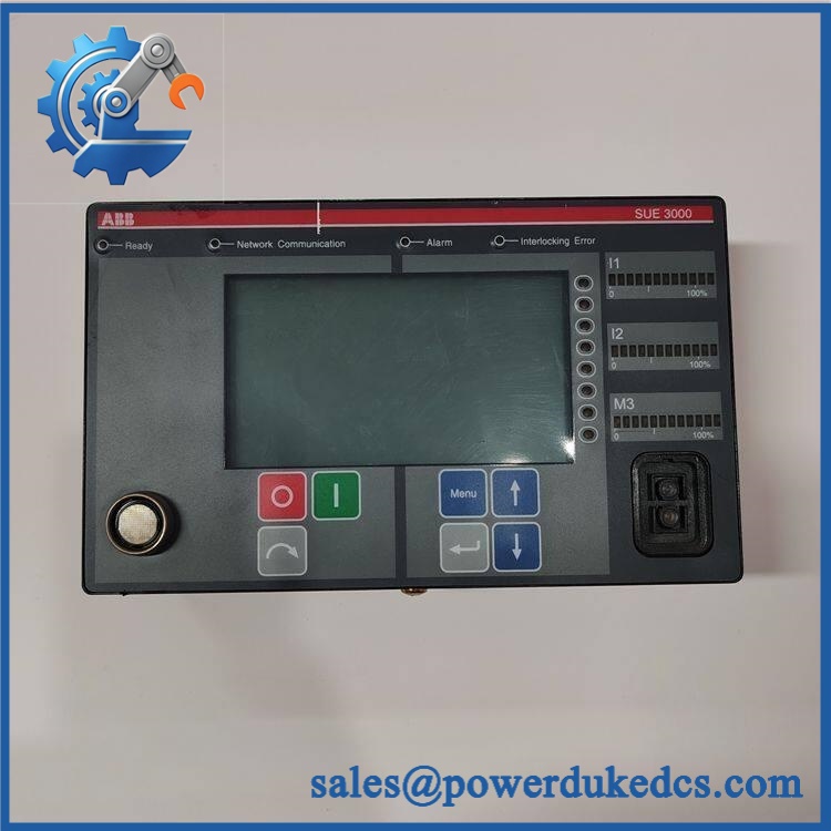
ABB SUE3000
Module 4: Dynamic Emergency Swap & Configuration Guide
1. Pre-Swap Prep — Protect the transfer logic first
- Place the switchgear and affected auxiliary bus in the approved maintenance condition.
- Confirm which source is supplying the critical bus before beginning work.
- Apply lockout/tagout to the applicable auxiliary/control circuits.
- Verify the SUE3000 auxiliary supply is isolated before opening the central unit.
- Export or record the existing configuration and project-specific transfer parameters.
- Record the exact hardware configuration, including CPU, power supply, I/O boards, communication board, and HMI.
- Photograph terminal wiring, board positions, and communication connections.
- Establish a controlled transfer-bypass procedure so loss of the does not create an unintended breaker operation.
ABB documentation identifies the central unit as containing the CPU board, power supply, binary I/O boards, analog input board, optional communication board, optional analog I/O board, and backplane.
2. Removal — Card-level construction matters
- Confirm auxiliary power has been isolated and verified.
- Disconnect the HMI and external communication interfaces as applicable.
- Identify the installed card positions before removing anything.
- Disconnect the relevant I/O wiring only after marking every terminal.
- Release the appropriate retaining hardware or card guides.
- Withdraw the affected card or central-unit assembly without stressing the backplane.
- Protect exposed connectors against contamination and ESD.
- Inspect the backplane and neighboring cards for thermal damage, corrosion, or loose connectors.
ABB’s dedicated card-exchange instructions specify ESD protection, a small flat-blade screwdriver, and Torx drivers including T10, T8, and T15, and document card positions such as PS, BIO, AIM/AO, COM, and MB.
3. Installation & Configuration — Restore the transfer philosophy
- Verify the replacement hardware and exact card configuration.
- Install each card in its original designated position.
- Reconnect all binary I/O according to the recorded terminal schedule.
- Restore communication wiring for SPABUS, LON, Modbus, Ethernet, or IEC 61850 where fitted.
- Restore the project-specific configuration from the verified backup.
- Confirm both incoming-source measurement channels and busbar measurements are assigned correctly.
- Verify circuit-breaker position feedback and close/trip command mapping.
- Confirm transfer-mode selection and blocking/interlocking logic.
- Check source permissive conditions before enabling automatic transfer.
- Do not commission with factory-default transfer thresholds.
The operating documentation specifically notes that project-specific details and settings should come from the separate assembly-specific switching documents and data sheets.
4. Power-On Self-Test (POST) — Test the transfer chain, not just the display
- Restore auxiliary power under the approved commissioning sequence.
- Check the HMI for normal initialization.
- Verify the Ready indication.
- Confirm the absence of persistent IBB Error, Alarm, or Interlocking indications.
- Verify both source-voltage measurements and busbar measurements.
- Confirm both circuit breakers report the expected open/closed status.
- Test manual transfer under a controlled, non-process-critical condition.
- Verify automatic transfer initiation logic using the approved simulation method.
- Confirm the alternate source closes only when all permissive conditions are satisfied.
- Review event and disturbance records after the test.
- Return automatic transfer to service only after all interlocks and source checks pass.
The HMI provides status indications including Ready, IBB Error, Alarm, and Interlocking, while the operating documentation describes measurement, protection, control, alarm, event, and service functions.
Module 5: Quality Assurance & Testing SOP
The is a protection-and-transfer control system, so a basic power-up test is insufficient. QA must prove that measurements, breaker feedback, transfer initiation, interlocking, and communication all behave as configured.
1. OEM identity verification
- Verify ABB
- Verify
- Confirm exact central-unit and HMI configuration
- Compare board labels, revision codes, card positions, and connector layouts
- Perform OEM anti-counterfeit visual inspection
- Photograph all identification markings
2. Physical inspection
- Inspect the central-unit enclosure for impact, corrosion, and contamination
- Inspect CPU, power supply, I/O, communication, and backplane assemblies
- Check card retainers and connector seating
- Inspect HMI display and operating controls
- Check terminal blocks for loose or damaged conductors
- Inspect cooling/ventilation paths
- Verify that any fiber-optic interfaces are clean and protected
3. Electrical screening
- Verify auxiliary input voltage according to the installed configuration
- Confirm protective-earth continuity where applicable
- Check power-supply output rails using the approved service procedure
- Verify binary input/output continuity
- Check analog input channels using calibrated test signals
- Inspect watchdog and relay circuits
- Do not apply arbitrary insulation or hipot voltages to populated electronic assemblies
4. Functional testing
- Perform power-on self-test
- Check Ready, IBB Error, Alarm, and Interlocking status
- Verify feeder-voltage measurement
- Verify busbar-voltage measurement
- Test circuit-breaker position inputs
- Test breaker trip and close outputs using a controlled test setup
- Simulate source-voltage failure and transfer initiation
- Test all configured transfer modes
- Verify transfer blocking and permissive logic
- Verify alternate-source synchronization conditions
- Test SPABUS, LON, Modbus, or Ethernet communication where fitted
- Verify event and disturbance recording
- Perform I/O full-range simulation on applicable analog and binary channels
- Record transfer timing, relay states, measured voltages, communication status, and final results
ABB describes four configurable transfer modes and continuous supervision of the source, busbar, and breaker conditions. The complete HSTS configuration can achieve approximately 30 ms transfer time, so timing verification should be included when the installed system uses the high-speed arrangement.
5. Final QC release
- Independent QC sign-off
- Verified configuration backup retained
- ESD-safe packaging for replacement electronics
- Connector protection
- Final hardware/configuration cross-check
- Retain inspection photographs and functional-test records
- Release only after transfer logic and interlocking tests pass
Module 6: Maintenance & Reliability FAQ
Q1. Is ABB a direct drop-in replacement, or does it require a firmware flash?
Do not treat as a single universal hardware configuration. The central unit can contain different combinations of CPU, power supply, I/O, communication, and analog boards. Configuration and firmware must match the specific project. ABB documentation also provides a dedicated firmware service interface and configuration interface, so verify the installed software revision before replacement.
Q2. Is it safe to hot-swap the while the system is running?
Do not assume live replacement is permitted. The directly participates in breaker control and automatic source transfer. Its removal can therefore affect protection, interlocking, and transfer availability. ABB’s card-exchange documentation requires ESD protection and specific mechanical tools; follow the installation’s approved isolation procedure before card removal.
Q3. Will replacing the cause my current program or configuration to be lost?
The critical information is the project-specific transfer configuration. Back up transfer modes, voltage thresholds, frequency thresholds, breaker feedback mapping, interlocks, source permissives, communication settings, and timing parameters before replacement. ABB explicitly notes that project-specific details and settings should be taken from the separate assembly-specific documentation.
Q4. How fast can the transfer the critical bus?
The complete High Speed Transfer System can achieve a transfer time of approximately 30 ms, equivalent to about 1.5 cycles, when combined with the specified trigger devices and high-speed magnetic circuit breakers. The device alone should not be advertised as providing 30 ms under every switchgear configuration.
Q5. What should I verify before ordering a replacement?
Verify , central-unit configuration, HMI version, CPU and I/O board types, communication board, auxiliary supply, number of circuit breakers, transfer mode, and project-specific parameter set. Also determine whether the installation is configured for the approximately 30 ms HSTS arrangement or for a conventional transfer configuration. Those details determine whether a physically similar replacement will actually restore the required transfer performance.











 Start Chat


