

Description
- ABB SYNCHROTACT5 SYN5201A-Z | On-site MRO Buffer Stock for Generator Synchronization Cabinets
Product Core Brief
- Model: SYN5201A-Z V277, 3BHB006714R0277
- Brand: ABB
- Series: SYNCHROTACT 5 Synchronization System
- Core Function: Executes automatic paralleling between generators and utility grid under strict synchrocheck logic
- Type: Single-channel digital automatic synchronizer
- Key Specs: 7 groups of switchable parameter sets, 50/60/16 2/3 Hz adaptive, integrated voltage & frequency matcher
- Condition: New Surplus, non-refurbished
Product Introduction
Key Technical Specifications
| Parameter | Specification |
|---|---|
| Full Model Code | SYN5201A-Z V277 / 3BHB006714R0277 |
| Product Series | SYNCHROTACT 5 Single Channel Synchronizer |
| Supported Grid Frequency | 50 Hz / 60 Hz / 16 2/3 Hz |
| Synchronization Monitoring | Voltage difference, frequency slip, phase angle deviation |
| Parameter Storage | 7 configurable independent parameter sets |
| Communication Interface | RS485 / Modbus RTU, SynView PC tool connection |
| Digital Inputs | 8 configurable DI channels |
| Relay Outputs | 6 relay outputs; rated 5 A / 250 V AC |
| Operating Supply | 24 V DC |
| Operating Temperature | -20 °C ~ +60 °C |
| Protection Class | IP20, cabinet indoor installation |
| Configuration Method | Front keypad or SynView Windows software |
| Mounting Method | Standard panel rack mounting |
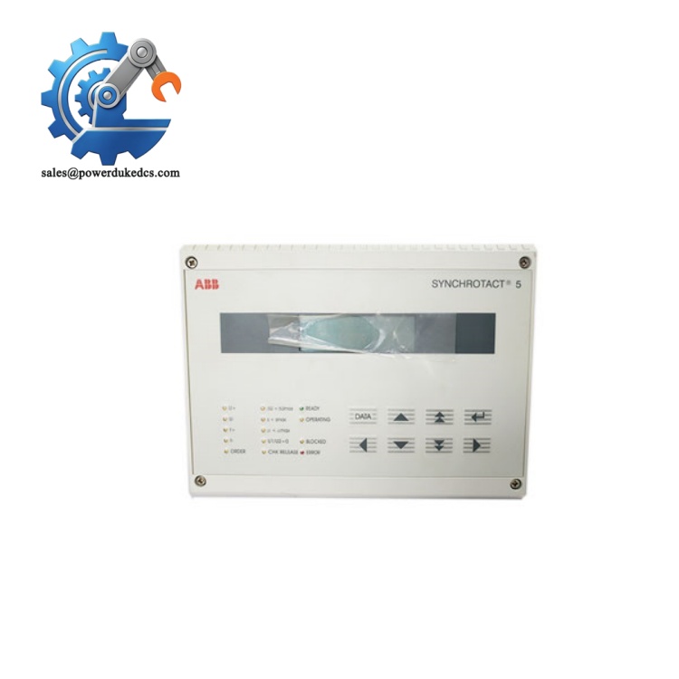
ABB SYNCHROTACT5 SYN5201A-Z
Quality Inspection SOP (Full Transparent Testing Process)
-
Warehouse Receiving Verification
Check serial number consistency with factory nameplate and traceability records. Full visual inspection to confirm no housing cracks, terminal corrosion, PCB disassembly marks or burnt components. Verify front display and operation buttons work normally.
-
Live Bench Functional Testing
Testing runs on dedicated ABB synchronization test rig. Complete power-on self-test and LED status validation. Simulate grid-generator voltage and frequency offset to trigger automatic matching logic. Execute full synchrocheck test and breaker closing sequence simulation. Run continuous 24-hour aging test to monitor stable operation.
-
Electrical Performance Testing
Use Fluke 115 multimeter for insulation resistance testing at 500 V DC. Verify all relay output contacts switch reliably without sticking. Check input circuit isolation performance to resist external voltage surges.
-
Firmware & Parameter Verification
Read and record built-in firmware version V277. Test switching between seven parameter sets to confirm all profiles load correctly. Capture screenshots of factory default configuration for customer reference. No unauthorized firmware modification will be performed.
-
Final QC & Packaging
Qualified units are sealed inside anti-static packaging with shockproof foam. QC Passed label with test date is attached. Test videos and screenshots can be shared for customer review before shipment.
Installation & Configuration Guide
Pre-Installation Preparation (15 mins)
Schedule generator unit shutdown and implement lockout-tagout protocol. Cut off all auxiliary control power inside synchronization cabinet. Wait minimum 10 minutes for internal circuit capacitors to fully discharge. Back up all active synchronizer parameters via SynView software.
Old Unit Removal (18 mins)
Disconnect low-power communication wires first, then remove voltage sampling terminals. Release rack fixing screws and slide the unit horizontally outward.
Inspect terminal blocks for oxidation or loose contacts. Dust on PCB connectors should be cleared using dry compressed air.
New Unit Installation (22 mins)
Mount the unit onto panel rack and fasten fixing screws evenly. Reconnect PT sampling cables, DI/DO wiring and communication lines strictly following photographed layout.
All wiring terminals tightened; PT secondary circuit grounded properly; no loose wire strands inside cabinet.
Power-On & Functional Commissioning (40 mins)
Connect PC running SynView software to establish communication. Import saved parameter sets or reconfigure synchronizing threshold limits.
Carry out static simulation test to verify voltage matching, frequency matching and synchrocheck functions. Execute full dry run synchronization cycle without live generator connection. Maintain continuous operation for minimum 60 minutes without abnormal alarms.
Record unit serial number, firmware version and replacement date into plant maintenance logbook.
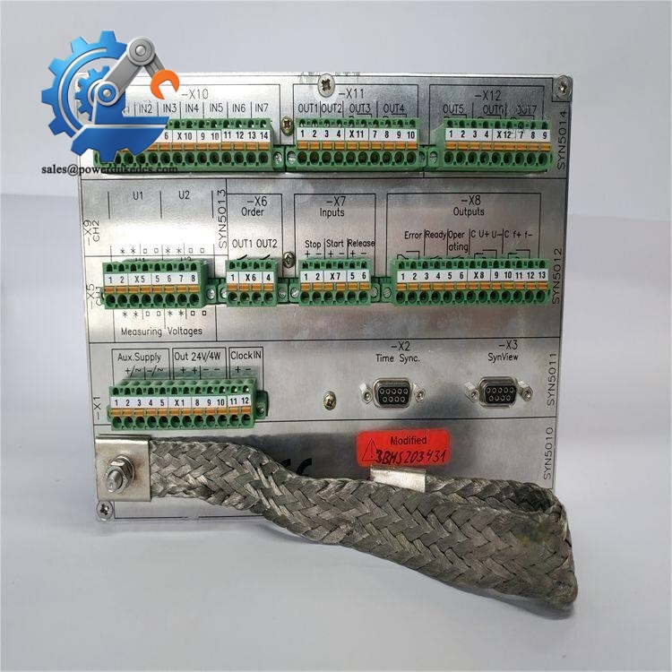
ABB SYNCHROTACT5 SYN5201A-Z
On-site Replacement Pitfall Guide (Engineer Practical Experience)
1. Firmware Version Compatibility Gap
Solution: Confirm exact required firmware version V277 before purchase. Request supplier confirm version matching.
2. PT Secondary Wiring Polarity Error
Solution: Mark positive/negative PT terminals clearly during removal. Conduct polarity verification before powering on new unit.
3. Wrong Parameter Set Selection
Solution: Label parameter set selection digital inputs on cabinet wiring diagram; test each profile during commissioning.
4. Ignored ESD Protection
Solution: Wear ESD wrist strap every time the cabinet door is opened for module handling.
5. Improper Relay Load Matching
Solution: Check relay coil power consumption against module output specification; add intermediate relay if load exceeds contact rating.
Frequently Asked Questions (FAQ)
A: Hot swap is not permitted. Interruption of PT sampling signals will trigger protection logic. Full cabinet power shutdown is required for safe replacement.
A: No. SYN5202 uses dual redundant channel architecture. Hardware I/O definition and safety logic differ. Direct replacement without cabinet modification is not possible.
A: Front panel display blackout; inability to detect generator voltage; failure to activate frequency/voltage matching; synchrocheck always blocked even under synchronous conditions; no closing pulse output when all conditions are met.
A: Parameter file import works normally if both units run V277 firmware. Different software revisions require manual reconfiguration of all synchronizing limits.
A: It is classified as critical slow-moving power equipment spare part. Maintain 1 unit buffer stock per power station to offset long OEM lead time. Negotiate consignment inventory terms to lower capital occupation.
A: Damage caused by PT secondary short-circuit, reverse power connection, lightning surge, condensation moisture, unauthorized disassembly, static discharge and incorrect wiring. Every unit completes bench synchronization testing prior to shipment.











 Start Chat


