

Description
- Brand: ABB
- Full Model Number: UUD148AE01
- ABB Part Number: 3BHE014185R0001
- Product Type: Voltage Transducer Control Board
- Lifecycle Status: Legacy PCS6000 power-converter spare; exact revision requires verification
- Core Function in System: Voltage measurement/transducer interface within ABB PCS6000 converter equipment
- Top 3 Hardcore Specs: PCS6000 application | Voltage transducer function | Jumper-configured hardware
- Replacement Configuration: Jumper positions must match electrical drawings
- Application: PCS6000 medium-voltage/high-power converter systems
- Condition & Lead Time: New, refurbished, or surplus stock subject to revision and test verification; expedited dispatch for stocked units
ABB’s PCS6000 service documentation identifies UUD148AE01, SAP number 3BHE014185R0001, as a Voltage Transducer and explicitly states that replacement requires the technician to set jumpers according to the electrical drawings.
Module 3: Technical Intro & Downtime Impact
A voltage-transducer board failure can create a much larger converter problem than the board’s physical size suggests. In a PCS6000 installation, incorrect or missing voltage feedback can prevent the control system from establishing trustworthy electrical measurements, potentially blocking startup or generating converter protection and monitoring faults. ABB’s service manual specifically identifies UUD148AE01 as the voltage-transducer component used in the system and treats it as a serialized replacement item.
For MTTR planning, the most important issue is configuration accuracy. ABB’s service procedure does not call for generic board replacement alone; it specifically instructs technicians to set the jumpers according to the electrical drawings after replacement. Publicly available primary documentation retrieved for this part does not provide a dependable standalone MTBF value, exact measurement range, or universal supply specification for every UUD148AE01 installation. Those values should therefore be taken from the applicable electrical drawing and converter documentation rather than estimated. That distinction matters in a high-energy converter, where an apparently small voltage-sensing mismatch can produce an invalid feedback condition.
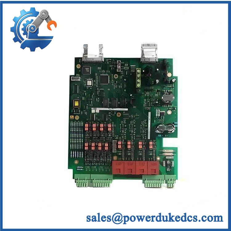
ABB UUD148AE01 3BHE014185R0001
Module 4: Dynamic Emergency Swap & Configuration Guide
1. Pre-Swap Prep — Isolate the and Capture Jumper Positions
This board is part of a high-power converter system. Apply the plant’s approved shutdown and LOTO procedure, isolate the converter, and verify the absence of hazardous voltage before accessing the electronics.
Record the complete UUD148AE01 / 3BHE014185R0001 identification, PCB revision, serial number, connector locations, wiring references, and every existing jumper position. ABB specifically requires jumper settings to follow the applicable electrical drawings. Photograph the original board before removal.
2. Removal — Disconnect the Board Without Disturbing Adjacent Transducer Wiring
After the converter has been made electrically safe, identify and label all board connections before disconnecting them. Release the board from its mounting arrangement using the specified hardware and withdraw it without flexing the PCB or stressing adjacent signal wiring.
Inspect the connector interfaces for oxidation, contamination, loose pins, and heat damage. Because this board participates in voltage measurement, a damaged connector can produce symptoms that resemble a defective transducer board.
3. Installation & Configuration — Reproduce the Approved Jumper Pattern
Install the replacement UUD148AE01 in the original location and restore every electrical connection according to the drawing. Check the part identification again before applying power.
The critical configuration step is the jumper arrangement. ABB’s service manual explicitly states that, during replacement, the technician must set jumpers according to the electrical drawings. Do not copy settings from a visually similar board unless the converter drawing confirms that they are identical. A field note: the same part number can appear in different service contexts, so the host converter documentation remains the controlling reference.
4. Power-On Self-Test (POST) — Validate Measurement Before Release
Restore control power under the approved commissioning procedure. Check for converter startup alarms, transducer-related faults, or abnormal diagnostic conditions.
Then compare the voltage measurements reported by the control system against known reference values or a calibrated test source, using the site’s authorized commissioning procedure. Confirm that all relevant voltage channels are present, stable, and correctly scaled before enabling normal converter operation. Do not treat a simple “board powers up” result as a successful acceptance test; this component’s purpose is measurement.
Module 5: Quality Assurance & Testing SOP
Each available ABB / 3BHE014185R0001 should undergo a controlled inspection and functional verification sequence before shipment:
- OEM anti-counterfeit visual inspection — verify ABB markings, identification, 3BHE014185R0001 number, PCB labels, connectors, mounting features, and manufacturing markings.
- Part-number reconciliation — compare the physical board with the customer’s BOM and service documentation.
- Revision and serial-number inspection — record PCB revision, serial number, date code, and any option or configuration identifiers.
- Jumper audit — photograph and record every jumper position; compare the configuration against the customer’s electrical drawing. ABB specifically requires jumper settings to follow the electrical drawings during replacement.
- Connector inspection — check all signal connectors for bent pins, oxidation, cracked housings, loose terminals, and evidence of overheating.
- Insulation and grounding checks — perform the applicable safety tests at laboratory-approved levels before applying operational power.
- Controlled power test — energize the board through a compatible test arrangement and verify stable operation.
- Power-on self-test (POST) checking for converter diagnostics — confirm the board does not generate transducer-related diagnostic faults.
- Voltage-input simulation — apply calibrated test signals appropriate to the specific configuration and verify the expected measurement response.
- Full-range measurement verification — where the test fixture supports it, verify the complete specified measurement range from the applicable electrical documentation rather than relying on a single-point reading.
- Scaling and channel verification — compare measured values against the calibrated reference and document deviation for every applicable channel.
- Noise and stability test — operate the board under sustained conditions and monitor measurement stability, drift, and abnormal fluctuations.
- Converter-interface test — verify that the control system correctly receives the voltage-transducer feedback.
- Fault-response test — where authorized by the test procedure, simulate an out-of-range or disconnected sensing condition and verify the expected diagnostic response.
- Final QA record — retain identification photographs, jumper configuration, calibration results, diagnostic status, test conditions, and final packaging photographs.
ABB’s service manual provides an important replacement control point: , and the replacement procedure requires the technician to configure its jumpers against the electrical drawings. That should be reflected in the supplier’s QA record rather than omitted as a generic “tested OK” statement.
Module 6: Maintenance & Reliability FAQ
Is the ABB 3BHE014185R0001 a direct drop-in replacement, or does it require a firmware flash?
It is a hardware replacement component for the voltage-transducer function. There is no evidence in the retrieved ABB service documentation that the board itself requires a conventional firmware flash. The critical replacement task is configuration: ABB specifically instructs technicians to set the jumpers according to the electrical drawings.
Is it safe to hot-swap the while the is running?
No. Do not treat this as a hot-swappable control card. The is installed within a converter system that contains hazardous electrical energy. Use the approved shutdown, isolation, discharge, and LOTO procedure for the specific converter before removing the board.
Will replacing the cause my program to be lost?
The is identified by ABB as a voltage transducer, not the main application controller. Replacing the board should not by itself constitute replacement of the converter’s application program. However, preserve the existing converter configuration and electrical drawings before maintenance, and verify the replacement’s jumper arrangement carefully. An incorrect jumper configuration can produce invalid voltage feedback even when the board is otherwise functional.
What should I verify before ordering an emergency spare?
Verify the complete identification / 3BHE014185R0001, the converter model, board revision, serial information where applicable, connector arrangement, and the jumper configuration shown on the converter’s electrical drawings. ABB’s service manual specifically lists this part as a serialized voltage transducer and calls for jumper configuration during replacement. A clear photograph of the installed board and its jumper area is particularly valuable for matching emergency stock.
What are the warranty terms if the board fails after installation?
Warranty depends on the supplying party, stock condition, and purchase agreement. Confirm the warranty period, DOA coverage, testing scope, and return procedure before shipment. Keep the pre-shipment test report, jumper photographs, serial-number record, and post-installation measurement results. For a voltage-transducer board, those records help distinguish an internal board fault from an incorrect jumper setting, wiring problem, or measurement-chain issue.











 Start Chat


