

Description
- Brand: ABB
- Full Model Number: XVC769AE101
- ABB Product ID: 3BHE006373R0101
- ABB Type Designation: OEI-BOARD, COATED
- Lifecycle Status: Legacy/field spare; current availability subject to stock confirmation
- Core Function in System: Optical Electrical Interface (OEI) board
- Top 3 Hardcore Specs: Coated PCB; 0.10 kg net weight; optical/electrical interface function
- Documented Application: ABB ACS2000 medium-voltage drive
- Condition & Lead Time: Inventory condition and dispatch time to be confirmed against the physical unit
ABB’s own ACS2000 spare-parts documentation identifies 3BHE006373R0101 as an Optical Electrical Interface (OEI) Board. The same ABB documentation lists one unit in the relevant cabinet assembly.
Module 3: Technical Intro & Downtime Impact
When an ABB medium-voltage drive loses its optical/electrical interface board, the fault can interrupt control or communication functions even though the higher-level controller and power section remain intact. The ABB XVC769AE101, ABB Product ID 3BHE006373R0101, is documented by ABB as an Optical Electrical Interface (OEI) Board for the ACS2000 spare-parts architecture. That makes exact part-number matching critical during an emergency repair.
For MTTR control, the most useful verified figures are the physical and identification data. A supplier record identifies the board as OEI-BOARD, COATED with a 0.10 kg net weight; however, ABB’s documentation does not establish a universal operating voltage, memory capacity, or operating-temperature specification for this board. Avoid importing specifications from unrelated XVC variants. Before replacement, match the ABB product ID, board designation, connector arrangement, and drive configuration.
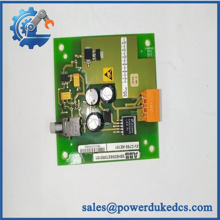
ABB XVC769AE101
Module 4: Dynamic Emergency Swap & Configuration Guide
1. Pre-Swap Prep
- Execute the ABB-approved shutdown and lockout/tagout procedure for the medium-voltage drive.
- Verify the DC-link and other hazardous voltages have fallen to the permitted service level.
- Photograph the failed XVC769AE101 / 3BHE006373R0101, including cable routing, connectors, labels, and board orientation.
- Use ESD protection and an antistatic work surface.
2. Removal
- Open the drive cabinet only after electrical isolation and discharge verification.
- Label each connected optical/electrical interface before disconnecting it.
- Release the board’s retaining hardware and withdraw the PCB using the designated mechanical points.
- Never pull directly on optical fibers or connector bodies.
3. Installation & Configuration
- Confirm the replacement marking XVC769AE101 / 3BHE006373R0101 before installation.
- Compare the replacement PCB, coating, connector locations, and revision markings with the removed board.
- Reconnect each interface to its original position and restore all retaining hardware.
- Verify fiber routing and bend radius before closing the cabinet.
4. Power-On Self-Test (POST)
- Re-energize the drive following the OEM startup sequence.
- Check the drive’s diagnostics for interface, communication, or optical-link faults.
- Verify expected communication status before enabling the power stage.
- Run the applicable drive functional test and confirm stable operation under normal control conditions.
ABB’s ACS2000 spare-parts manual specifically identifies this part as the OEI Board, so interface integrity is the key post-installation verification point.
Module 5: Quality Assurance & Testing SOP
Identity and authenticity inspection
- ABB part-number verification: 3BHE006373R0101
- Type-designation verification: OEI-BOARD, COATED
- OEM label, serial/traceability, and marking inspection
- PCB condition, conformal coating, connectors, mounting points, and solder-joint inspection
- Comparison against documented ABB OEI construction and supplied photographs
Electrical and interface screening
- Controlled power-up using an appropriate test fixture
- Power-on self-test observation
- Optical interface continuity and connection inspection
- Electrical interface continuity checks
- Communication/link-status verification where a compatible ABB drive test environment is available
Functional validation
- Drive-side diagnostic scan
- Interface fault monitoring
- Control-system communication check
- Application-specific functional test under controlled conditions
- Record abnormal status indications rather than relying only on a visual pass
Final QC release
- Technician inspection sign-off
- Antistatic packaging
- Connector protection
- Shock-resistant outer packaging
- Part number and quantity cross-check
- Test record retained with shipment documentation
ABB’s spare-parts documentation provides the strongest baseline identification: 3BHE006373R0101 = Optical Electrical Interface Board, with a cabinet quantity of one in the cited ACS2000 assembly.
Module 6: Maintenance & Reliability FAQ
Is the ABB XVC769AE101 a direct drop-in replacement?
It should only be treated as a direct replacement when the installed drive configuration, board identification, revision, and interfaces match. ABB identifies 3BHE006373R0101 specifically as an Optical Electrical Interface (OEI) Board.
Is it safe to hot-swap the XVC769AE101 while the drive is running?
Do not assume that it is. This board is associated with ABB medium-voltage drive equipment, where hazardous voltage and stored energy remain major service concerns. Follow the applicable ABB service procedure and verify electrical isolation before board removal.
Will replacing the OEI board require a firmware flash?
The available ABB spare-parts documentation identifies the hardware and its function but does not establish a universal firmware requirement for . Therefore, do not perform an undocumented firmware update merely because the PCB was replaced. Record the existing drive and controller software versions first.
Will replacing this board erase my current program or drive parameters?
The OEI board should not be assumed to contain the complete application configuration. Before replacement, preserve the drive parameter set, fault history where available, relevant controller configuration, and photographs of existing hardware settings. After installation, compare diagnostics and configuration against the pre-failure record.
What warranty applies if the replacement fails after installation?
The warranty period should be stated in the purchase documentation. For a critical spare, confirm the warranty duration, installation-related exclusions, return procedure, and whether a pre-shipment test record is provided before the unit is released.











 Start Chat


