

Description
- Brand: Woodward / Baumüller
- Full Model Number: BUM60-1224-54-B-001-VC-A0-0093-0013-G003-0000
- Associated Woodward P/N: 3522-1004
- Lifecycle Status: Legacy / previous-generation EM-80/EM-300 driver; Woodward documents retrofit paths from 3522-1004 to newer driver hardware
- Core Function: EM-80/EM-300 brushless electric actuator driver / servo controller
- Top 3 Technical Specs: 3-phase 400–480 VAC | 15 kVA output rating | 4.5 kW typical motor power
- Control Interface: 4–20 mA analog input | 1–5 V analog position output | 24 V control I/O
- Stock & Condition: New surplus / tested refurbished; exact configuration and physical stock require lot-level confirmation
Module 3: Obsolescence & Supply Chain Deep Dive
A failed Woodward BUM60-1224-54-B-001 can create a significant outage because the unit is part of the EM-80/EM-300 electric actuator system rather than a standalone generic variable-frequency drive. Woodward’s own manual identifies the EM system as an actuator, driver, required cabling, and associated power/interface hardware. The driver accepts three-phase AC input and provides controlled power to the actuator, while also handling position feedback and control signals. The documented driver specification includes 15 kVA output power, 4.5 kW typical motor power, and a 400–480 VAC three-phase supply architecture.
For an installed EM-80/EM-300 system, locating an exact legacy driver can have a much lower TCO than replacing the complete actuator/control chain. Existing cabinet wiring, actuator mechanics, resolver cabling, governor interfaces, mechanical linkage and commissioning records can potentially remain in service. Woodward explicitly documents 3522-1004, 3522-1005 and 3522-1009 as previous EM-80/EM-300 driver models and points customers toward a conversion procedure when migrating to newer hardware such as 3522-1042. That distinction matters: an exact surplus 3522-1004 is generally a like-for-like maintenance solution, whereas a newer driver should be treated as a retrofit project with configuration and wiring review.
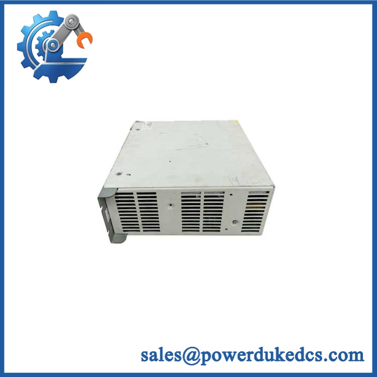
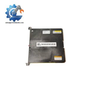
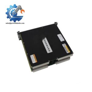
Woodward BUM60-1224-54-B-001 3522-1004
Module 4: Compatibility & Replacement Matrix
| Approval Point | Assessment |
|---|---|
| Replacement Class | Drop-in replacement for an identical BUM60 / 3522-1004 configuration |
| Modern Replacement Path | Hardware retrofit when migrating to a newer Woodward driver such as 3522-1042 |
| Software Compatibility | Configuration verification required; drive parameters and application setup must match the actuator |
| Hardware Modification | None expected for exact 3522-1004 replacement; retrofit may require wiring/configuration changes |
| AC Input | 3-phase 400–480 VAC, per Woodward driver-system documentation |
| Motor Capability | 15 kVA output / 4.5 kW typical motor power |
| Analog Input | 4–20 mA, 15-bit resolution |
| Position Feedback Output | 1–5 V corresponding to 0–100% shaft position |
| Estimated Switch Time | ~2–4 hours for like-for-like driver replacement and functional checks |
| Retrofit Engineering Time | ~1–3 days is a reasonable planning allowance for engineering review, wiring verification, parameter setup and commissioning; site complexity can extend this |
| TCO Position | Exact legacy spare usually has the lowest immediate outage cost; newer-driver retrofit requires broader engineering |
Woodward specifies a maximum 100 m distance between driver and actuator and requires separate three-phase motor power and position-sensor connections. The driver is designed for mounting inside the control cabinet rather than directly on the engine.
Field Traps — Watch Out
Feedback mismatch: The driver depends on the actuator’s position-sensor/resolver circuit. Woodward’s troubleshooting procedure specifically identifies resolver errors and instructs technicians to inspect the feedback cable and actuator wiring.
Parameter or firmware mismatch: Woodward documents a specific “Param.consistency” fault and a “Firmware” configuration error. A replacement driver therefore should not be commissioned solely by matching the enclosure and part number; the approved parameter set must be checked.
Input-power hazard: This is not a 24 VDC-only servo drive. The EM system uses three-phase 400–480 VAC power, together with a separate 24 VDC control supply.
Module 5: Quality Assurance & Testing SOP
For a high-power actuator driver, a successful bench power-up is only the first inspection gate. The acceptance procedure should reproduce the actual control and feedback path wherever the test facility permits.
- Part identity verification: Record Woodward markings, complete BUM60-1224-54-B-001-VC-A0-0093-0013-G003-0000 identification, associated 3522-1004 number, serial number and revision data.
- OEM anti-counterfeit visual inspection: Inspect the nameplate, housing, connectors, PCB markings, fasteners and evidence of unauthorized repair or component substitution.
- Mechanical inspection: Check mounting points, terminal blocks, cooling surfaces, connector locks and enclosure integrity.
- Insulation and grounding checks: Verify protective-earth continuity and perform the applicable insulation checks before high-voltage energization.
- DC control-power verification: Confirm the 24 V control supply circuit and monitor startup behavior.
- AC input test: Energize using an appropriately protected three-phase 400–480 VAC test source and verify abnormal current or fault conditions are absent.
- Power-on self-test: Record startup diagnostics, keypad/display indications and readiness/fault status.
- 4–20 mA command test: Apply calibrated current inputs and verify the driver’s response to representative command values. Woodward specifies 15-bit input resolution and fault detection below 3.6 mA and above 24 mA.
- Position-feedback test: Verify resolver communication and confirm correct actuator-position feedback with a compatible actuator or approved simulator.
- Motor-output test: Connect the specified actuator/motor and verify controlled three-phase output, acceleration and steady-state operation without abnormal current or fault events.
- Position-output verification: Confirm the analog position output tracks the expected 1–5 V / 0–100% shaft-position relationship.
- Fault-response testing: Test representative enable, E-stop, reset, motor-connection, resolver and parameter-consistency conditions.
- Thermal/load observation: Operate under representative load long enough to identify abnormal heating, vibration, current imbalance or intermittent trips.
- Final QC release: Record input voltage, control current, analog-command response, feedback status, output behavior, fault codes and serial traceability before shipment.
Woodward’s manual specifically warns that actuator movement can occur when power is first applied, and it requires appropriate safety controls around the higher-level protection system.
Module 6: Procurement & Lifecycle FAQ
1. Is the Woodward BUM60-1224-54-B-001 / 3522-1004 genuinely in stock, and what is the emergency-shipping cutoff?
Current commercial listings show this exact BUM60 configuration and associated 3522-1004 identifier, but online availability should not be treated as proof of physically verified warehouse stock. For emergency procurement, require an actual-unit photograph, complete nameplate, serial number, quantity, condition, functional-test status and same-day carrier cutoff before releasing the PO.
2. How do you verify the condition and authenticity of a surplus 3522-1004?
Require complete Woodward/part-number identification, serial traceability, enclosure and PCB inspection, protective-earth verification, controlled AC energization, 4–20 mA simulation, resolver/feedback testing and motor-output testing. The final report should document actual measurements and fault results rather than simply stating “tested.”
3. Are firmware or parameter compatibility issues important before issuing the PO?
Yes. Woodward’s troubleshooting section explicitly includes parameter-consistency and firmware configuration faults. The replacement therefore needs to be checked against the installed actuator configuration and approved parameter set before commissioning.
4. Can 3522-1004 be replaced directly by a newer Woodward driver?
Not as an automatic one-for-one assumption. Woodward identifies 3522-1004 as a previous EM-80/EM-300 driver and states that replacement by a newer version such as 3522-1042 is covered by a dedicated driver-conversion procedure. That makes the newer unit a retrofit path, not simply a catalog-number substitution.
5. What warranty and return terms should procurement require?
The PO should specify the complete BUM60-1224-54-B-001-VC-A0-0093-0013-G003-0000 / 3522-1004 identification, accepted condition, tested operating range, warranty duration, DOA definition and return period. For this driver, acceptance should include AC input, 4–20 mA command, resolver feedback and actuator-output verification because those functions are central to the EM-80/EM-300 system.



 Start Chat


