

Description
- Brand: DEIF
- Full Model Number: DU-2/MKIII
- System/Series Family: DEIF Multi-line 2 / AGC-4 / PPM-3 / PPU
- One-Sentence Core Function: Operator display and control unit for monitoring and operating generator-set power management systems
- Top 3 Hardcore Specs: 24 VDC nominal supply; 8–26 VDC operating range; approximately 3 W maximum consumption
- Stock Status: Stock condition and exact hardware revision to be confirmed
Module 3: Technical Product Introduction
When a generator controller remains operational but the operator loses access to voltage, frequency, current, power, alarms, or control commands, the display unit can become the practical failure point. The DEIF DU-2/MKIII is a Multi-line 2 display and operator interface used with DEIF generator control and power-management equipment. It provides local visualization of system parameters and access to operating and configuration functions, working with compatible controllers such as AGC-series and PPM/PPU equipment. DEIF-related documentation and current technical references identify DU-2/MKIII as a display unit for these generator-management applications.
The unit operates from a 24 VDC nominal auxiliary supply, with an available operating range reported as 8–26 VDC and maximum consumption of approximately 3 W. Current technical references identify a front-panel protection level of IP52, with higher protection possible using the specified sealing option; the rear of the unit remains IP20. The display is intended for real-time presentation of electrical and generator parameters, with communication to the host controller handled through the system’s dedicated interface. Exact communication wiring and controller compatibility should be checked against the installed Multi-line 2 configuration before replacement.
Module 4: Application Scenarios & Field Realities
- In marine generator switchboards, the DU-2/MKIII provides the local operator interface for generator and switchboard parameters. DEIF documentation and project specifications show the unit used with generator control systems supplied for marine and industrial applications, where operators need direct access to electrical measurements and alarm information.
- For multiple-generator paralleling systems, the display can be used to monitor parameters such as voltage, current, frequency, power, and power factor while the host controller manages synchronization and load sharing. Check the connected controller type before replacement because the display’s usable functions are determined by the host system configuration.
- During generator maintenance, the DU-2/MKIII can act as a diagnostic access point rather than simply a screen. Alarm and event information can help separate a controller problem from a field-measurement or generator-side fault, reducing unnecessary replacement of healthy controller hardware.
- Where redundant operator interfaces are required, DEIF system references identify configurations using one or two DU-2/MKIII units depending on the intended redundancy arrangement. A second display therefore should not be added or removed without checking the corresponding system configuration and communication architecture.
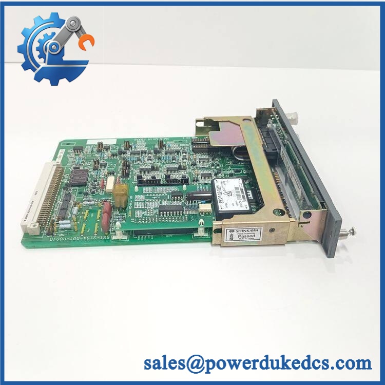
DEIF DU-2/MKIII
Module 5: Migration, Compatibility & Installation Traps
Replacement Matrix
Replacement Classification: Drop-in Replacement Within the Matching DEIF Multi-line 2 Configuration
A like-for-like DU-2/MKIII replacement is generally suitable when the existing installation uses the same DEIF Multi-line 2 display architecture, compatible mounting arrangement, controller family, communication interface, and firmware/configuration baseline. The display is an operator interface, so compatibility depends heavily on the host controller and system software.
DU-2/MKIII → TDU display: Configuration Review Required. DEIF documentation indicates that a TDU can be used instead of a DU-2 in some systems, but this should be treated as a system-level substitution rather than a universal electrical drop-in exchange.
DU-2/MKIII → Generic HMI: Hardware Modification Required. A generic HMI cannot be assumed to reproduce DEIF’s controller-specific menus, alarm handling, parameter access, communication protocol, or operating functions.
⚠️ Field Traps — Watch Out
1. Host-controller dependency: DU-2/MKIII is not a standalone generator controller. Its available measurements, menus, alarms, and control commands depend on the connected DEIF equipment and system configuration.
2. Supply-voltage margin: The nominal supply is 24 VDC, with current references specifying 8–26 VDC operating voltage. Measure voltage directly at the display terminals during startup and under cabinet load; a weak DC supply can produce intermittent resets that resemble a display failure.
3. Front-versus-rear protection: The cited protection levels differ between the front and rear of the unit. The front can reach IP52, while the rear remains IP20 unless the installation provides the required environmental protection. Do not treat the display as a fully sealed enclosure.
4. Redundant display configuration: Systems using two display units require the appropriate communication and redundancy configuration. Installing two displays physically does not automatically establish a valid redundant operating arrangement.
Module 6: Quality Assurance SOP
Each DEIF DU-2/MKIII should undergo a documented display, communication, and operator-interface test before shipment.
- OEM identification visual inspection: Verify DEIF markings, DU-2/MKIII designation, serial number, hardware revision, front-panel labels, connector arrangement, keypad/buttons, and display assembly.
- Configuration capture: Record the complete model and hardware revision, plus the connected DEIF controller type when the unit is supplied as part of a system spare.
- Mechanical inspection: Examine the front bezel, LCD/display area, buttons, mounting points, rear connector, enclosure, and sealing surfaces for cracks, deformation, corrosion, contamination, or impact damage.
- Power verification: Apply a controlled 24 VDC supply and verify stable operation across the documented operating range. Record startup current and any abnormal resets.
- Power-on self-test (POST): Confirm normal initialization, display activation, keypad response, alarm indication, and diagnostic startup behavior.
- Display verification: Confirm that voltage, current, frequency, power, power factor, alarms, and other parameters provided by the connected controller are rendered correctly.
- Communication handshake verification: Connect the display to an approved DEIF controller test setup and verify reliable bidirectional communication.
- Operator-input test: Exercise every applicable front-panel button and confirm correct menu navigation, parameter access, alarm acknowledgement, and command transmission.
- Alarm and event test: Generate controlled test alarms through the host controller and verify that the DU-2/MKIII displays the correct alarm state and event information.
- Parameter-access test: Verify representative read/write or setup functions permitted by the installed controller configuration and ensure that unauthorized changes are not introduced during testing.
- Redundant-display test: Where required, test the unit in a dual-display configuration and verify the expected primary/secondary behavior and communication status.
- Backlight/display-quality inspection: Check for missing pixels, abnormal characters, uneven illumination, display flicker, or contrast problems across the usable screen area.
- Communication-loss test: Simulate an approved communication interruption and verify the expected loss-of-communication indication without causing an uncontrolled generator command.
- Extended stability test: Run the display continuously with representative controller data and repeated operator interactions while monitoring communication stability and power consumption.
- Environmental inspection: Verify the front sealing arrangement where the installation relies on the enhanced front-panel protection and confirm that the rear of the unit is appropriately protected by the cabinet.
- Final QC record: Retain complete part-number photographs, hardware revision, supply measurements, display test results, communication results, alarm tests, keypad tests, redundancy results where applicable, and final QC approval.
The DEIF DU-2/MKIII is a Multi-line 2 operator display and control unit used with DEIF generator-management systems. Current technical references identify 24 VDC nominal supply, 8–26 VDC operating voltage, approximately 3 W maximum consumption, IP52 front protection with the applicable sealing arrangement, and IP20 rear protection.
For spare-parts control, the decisive compatibility checks are the DU-2/MKIII hardware revision, connected DEIF controller family, communication interface, mounting arrangement, firmware/configuration baseline, supply voltage, and any redundant-display configuration. A display that powers up correctly is not sufficient evidence of compatibility; the operator menus, alarm handling, parameter access, and controller communication should all be verified before releasing the spare to a production generator system.











 Start Chat


