

Description
- Brand: DEIF
- Full Model Number: IPM-1
- System/Series Family: Delomatic-3
- One-Sentence Core Function: Input module for acquiring electrical measurements and status signals used by the Delomatic-3 power-management system
- Top 3 Hardcore Specs: 24 VDC nominal supply; AC voltage measurement capability; generator/bus electrical measurement and digital-status acquisition
- Stock Status: New Surplus / Fully Tested Refurbished — verify exact PCB revision and complete part number before shipment
Module 3: Technical Product Introduction
A failed measurement input module can make a generator controller appear to have a protection or synchronization problem when the primary issue is simply missing electrical feedback. The DEIF IPM-1 is an input module used in the Delomatic-3 architecture, where it handles measurement and input signals needed by the power-management system. DEIF maintains dedicated Delomatic-3 documentation for the IPM-1, while industrial inventory records identify IPM-1 with DEIF part number 1044220070E.
Available technical records associate the IPM-1 with generator and bus measurements, including voltage, current, frequency, and status information. A current industrial listing identifies 24 VDC as the nominal supply and an AC voltage measurement capability extending to 500 V, while another inventory source confirms the 1044220070E association and identifies the item as a Delomatic input module. Because these detailed electrical values are not exposed on the current DEIF Delomatic-3 documentation index itself, the exact PCB revision and configured installation should be verified before treating every listed range as an OEM specification.
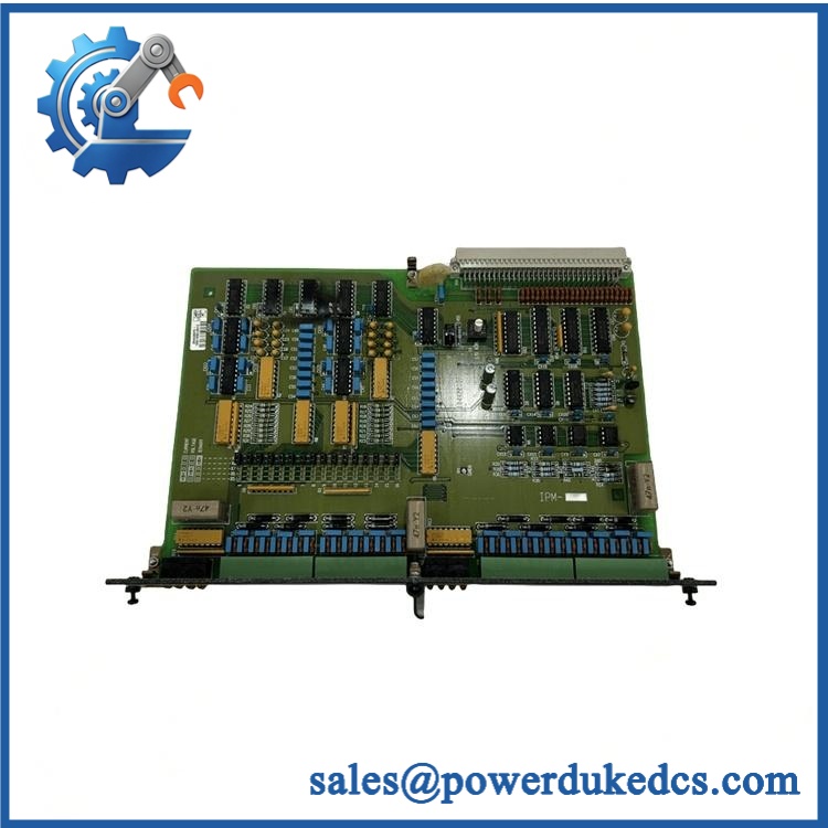
DEIF IPM-1
Module 4: Application Scenarios & Field Realities
- In generator-control panels, the IPM-1 sits on the measurement side of the Delomatic-3 architecture. When generator voltage, current, frequency, or breaker-related information suddenly disappears, check the and its field wiring before replacing the main controller.
- During synchronization or load-sharing troubleshooting, compare the electrical values available to the controller with independent measurements from calibrated instruments. A missing or distorted measurement can lead to incorrect conclusions about the generator or switchgear itself.
- For marine and offshore power systems, preserving the exact Delomatic-3 hardware revision is important. DEIF positions Delomatic within marine, offshore, and power-generation applications, and current parts records identify as part of that Delomatic input architecture.
- When managing legacy spares, record both and 1044220070E. Commercial inventory also shows related identifiers such as 1044220070C, so the complete label and revision should be captured before stock is released for a field replacement.
Module 5: Migration, Compatibility & Installation Traps
Replacement Matrix
| Replacement Type | Assessment |
|---|---|
| Drop-in Replacement | Conditional — suitable for a like-for-like replacement when the Delomatic-3 hardware revision and field configuration match |
| Software Compatible | Conditional — verify the Delomatic-3 application, I/O configuration, calibration data, and controller revision |
| Hardware Modification Required | Normally no for an exact replacement; measurement wiring, CT/PT arrangement, and connector assignment must match |
⚠️ Field Traps — Watch Out
1. Do not ignore the complete part number.
Current inventory sources associate with 1044220070E, while another source lists 1044220070C as an position variant. Treat the complete label and revision as the controlling spare identity.
2. CT/PT wiring must be preserved.
The is part of the electrical-measurement path. Incorrect CT polarity, PT wiring, phase sequence, or scaling can produce apparently believable measurements with the wrong phase relationship or magnitude.
3. Do not assume every public voltage range applies to every revision.
One current listing gives a 0–500 VAC measurement range and 24 VDC supply, but the available DEIF documentation index does not expose a dedicated data sheet in the retrieved material. Verify the physical unit and revision before publishing those values as universal specifications.
4. Preserve calibration and configuration information.
The replacement module should be tested against the application’s existing measurement scaling. A hardware replacement that passes a basic power-up check can still generate incorrect kW, kVAr, voltage, or frequency values if configuration data is inconsistent.
Module 6: Quality Assurance SOP
- OEM anti-counterfeit visual inspection — inspect DEIF identification, marking, PCB labels, serial information, connector construction, and visible manufacturing details.
- Exact part-number verification — confirm and, where present, the complete 1044220070E reference against the purchase order and physical label.
- Revision verification — record PCB revision, hardware revision, serial number, and any position/configuration code before testing.
- Host-system verification — confirm the target equipment uses the Delomatic-3 architecture and document the associated controller and cabinet configuration. DEIF maintains dedicated Delomatic-3 documentation and replacement instructions for .
- Mechanical inspection — inspect connectors, mounting points, PCB surfaces, terminals, and enclosure components for corrosion, contamination, cracked insulation, or mechanical damage.
- Power-on self-test (POST) — energize the using the verified Delomatic-3 supply arrangement and record startup behavior, status indications, current draw, and abnormal temperature rise.
- Voltage-input simulation — apply controlled AC measurement signals using a calibrated source and verify the corresponding measured values within the confirmed configuration range.
- Current-input simulation where applicable — use an approved CT/current simulator to verify the measurement path and confirm correct phase and magnitude handling.
- Frequency verification — apply calibrated test frequencies across representative operating points and compare the controller-reported frequency with the reference instrument.
- Digital-input verification — where the installed configuration includes breaker or status inputs, exercise each applicable input and confirm correct state recognition.
- Measurement-scaling verification — compare voltage, current, frequency, active-power, and reactive-power calculations against the approved Delomatic-3 configuration and calibrated reference instruments.
- Communication handshake verification — verify the ‘s data exchange with the compatible Delomatic-3 controller using the applicable DEIF system test procedure. This should be treated as a system-level verification rather than a generic Ethernet or CAN test unless the exact interface is documented.
- Protection-function validation — where supported by the approved test environment, verify that abnormal measurement conditions produce the expected Delomatic-3 alarms or protection responses without exposing the test equipment to uncontrolled fault energy.
- Final QC and packaging — document exact model, complete part number, hardware revision, calibrated measurement results, digital-input results, system-interface status, photographs, ESD protection, and packaging condition.
Engineering note: is supported as a Delomatic-3 input module, with current industrial records associating it with 1044220070E. DEIF’s own Delomatic-3 documentation portal confirms that an replacement instruction exists as part of the product documentation set. Public commercial records provide additional electrical details, including a 24 VDC supply and AC measurement capability, but those detailed values should be matched to the actual hardware revision before being treated as universal OEM specifications.











 Start Chat


