

Description
- DEIF TAP-210DG/3 | Factory Tested Generator Control Part
2. At-A-Glance Executive Brief
- Model: DEIF TAP-210DG/3
- Series: DEIF 210DG Transducer Series
- Part Type: Watt Transducer / Active Power Measurement Device
- Core Function: Converts measured electrical power values into standardized analog output signals for monitoring, control, and instrumentation systems.
- Key Specifications:
- Measures active power (Watt).
- DIN-rail mounting design.
- Supports AC measurement applications.
- Available with configurable current and voltage transformer ratios.
- Analog output options including current and voltage signals.
- Typical Procurement Category: Generator control spare, marine electrical measurement component, switchboard instrumentation asset.
3. Product Introduction
Installed inside electrical switchboards and generator control panels, the DEIF TAP-210DG/3 watt transducer converts three-phase electrical measurements into usable analog signals for supervisory systems. When this device fails, operators may see incorrect power readings, unstable load-sharing signals, or inaccurate generator monitoring values. In field deployments, technicians usually verify CT/PT wiring, auxiliary supply, and output loop conditions before replacing the transducer (measurement faults often originate outside the device).
The TAP-210DG/3 belongs to DEIF’s 210DG transducer family, designed for industrial and marine power measurement applications. The unit uses a DIN-rail mounting format and provides isolated signal conversion between measured electrical parameters and control-system inputs. This model has been phased out in DEIF’s current product program, so existing installations generally rely on controlled spare inventory or approved migration solutions.
4. Core Technical Specifications
| Parameter | Value |
|---|---|
| Manufacturer | DEIF |
| Model Number | TAP-210DG/3 |
| Product Type | Watt Transducer |
| Measurement Function | Active Power (Watt) |
| Installation Type | DIN Rail Mount |
| Network Type | Single-phase / three-phase configurations depending on variant |
| Measuring Voltage | Up to 440 VAC nominal range options |
| Measuring Current | 0.5–10 A AC input range |
| Frequency Range | 45–65 Hz (application dependent) |
| Output Signals | 0–1 mA, 0–5 mA, 0–10 mA, 0–20 mA, 4–20 mA, voltage outputs available |
| Accuracy Class | Class 0.5 according to IEC measurement requirements |
| Response Time | Less than 150 ms |
| Isolation | Galvanic measurement isolation |
| Auxiliary Supply | Variant dependent |
| Operating Temperature | Approx. -25°C to +70°C |
| Storage Temperature | Approx. -40°C to +70°C |
| Mounting Clearance | Minimum 10 mm recommended between devices |
| Weight | Approx. 0.5 kg maximum |
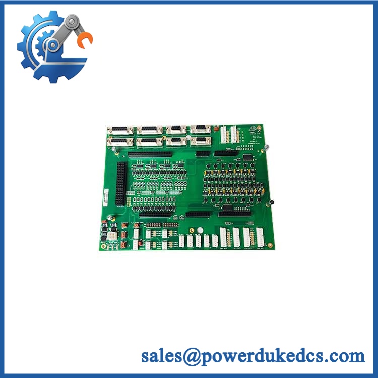
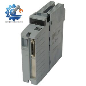
DEIF TAP-210DG/3
5. Application Scenarios & Pain Points
On marine generator switchboards, the TAP-210DG/3 provides active power feedback used for load monitoring, generator management, and operator displays.
For offshore power systems operating continuously, inaccurate watt measurement can affect load-sharing decisions and generator performance verification.
Within industrial distribution panels, the transducer converts CT/PT measurements into analog signals used by PLC, DCS, or monitoring equipment.
At facilities maintaining older DEIF installations, replacement availability becomes important because the TAP-210DG series has reached end-of-life status.
Without a calibrated power transducer, operators may receive incorrect kW values even when the generator and electrical protection equipment are functioning normally.
6. Common Error Codes & Diagnostic Symptoms
Symptom/Code: Power indication incorrect / kW value offset
→ Diagnosis: Possible incorrect CT/PT ratio setting, wiring error, or internal measurement circuit drift.
→ Action: Verify transformer ratios and replace the TAP-210DG/3 if measurement accuracy cannot be restored.
Symptom/Code: Analog output missing / 4–20mA loop inactive
→ Diagnosis: Possible auxiliary supply failure, output circuit fault, or disconnected terminal wiring.
→ Action: Check supply and loop continuity, then replace the transducer.
Symptom/Code: Unstable power signal during load changes
→ Diagnosis: Possible input connection problem or internal component aging.
→ Action: Inspect electrical connections and replace the unit if instability remains.
7. Cross-Reference & Lifecycle Migration
- Product Family: DEIF TAP-210DG watt measurement transducers.
- Related Models: TAP-210DG, TAQ-210DG (reactive power measurement), TAV-210DG (voltage measurement).
- Replacement Considerations:
- Confirm measurement range.
- Match CT/PT ratios.
- Verify auxiliary voltage.
- Confirm analog output type.
- Check physical DIN-rail installation requirements.
- Firmware Requirement:
No field firmware loading is normally required. Configuration is primarily hardware specification and calibration dependent. - Lifecycle Status: Obsolete / End of Life.
- DEIF has phased out the TAP-210DG product family.
- Maintain tested spare units for operating systems where replacement redesign is not yet completed.
8. Field Engineer’s Tech Notes (Anti-Pitfall Guide)
- Do not replace the transducer without checking CT polarity.
Incorrect current transformer direction can create reversed power readings that appear to be a failed measurement device. - Verify the exact output configuration before installation.
Different TAP-210DG/3 variants may use different output ranges and measurement settings. - Keep ventilation spacing around DIN-rail units.
Multiple tightly packed transducers can increase operating temperature and shorten component life.
9. Strict QA & Testing SOP
Step 1 — Incoming Inspection
- Verify DEIF label and TAP-210DG/3 marking.
- Record serial number and configuration data.
- Inspect terminals and housing condition.
Step 2 — Physical Examination
- Check DIN-rail clips.
- Inspect screw terminals.
- Verify no mechanical damage exists.
Step 3 — Electrical Testing
- Apply rated auxiliary supply.
- Simulate voltage and current inputs.
- Verify output signal response.
- Check measurement accuracy.
Step 4 — Calibration Verification
- Compare measured output against reference equipment.
- Record deviation values.
- Confirm output stability.
Step 5 — Packaging Control
- Use protective packaging.
- Prevent terminal damage during transport.
- Include inspection records.
Test videos are available for verification procedures when required.
10. Buyer’s FAQ (Dynamic Q&A)
Q: Can the DEIF TAP-210DG/3 be replaced while the switchboard is energized?
A: No. Isolate the measurement circuit and auxiliary supply before removal. CT circuits require special attention because incorrect handling can create dangerous voltage conditions.
Q: How do I confirm a genuine DEIF TAP-210DG/3 unit?
A: Check the DEIF label, model designation, terminal layout, configuration markings, and supplier inspection records.
Q: Does the TAP-210DG/3 require software configuration after replacement?
A: Normally no firmware loading is required. However, CT/PT ratios and output specifications must match the original installation.
Q: What should be requested when buying this discontinued transducer?
A: Request condition details, test records, photographs, storage history, and warranty terms. For obsolete electrical measurement devices, documented testing is important.
Procurement Note: The DEIF TAP-210DG/3 should be managed as a controlled electrical measurement spare. Keep the original configuration data, CT/PT settings, and switchboard documentation together to avoid commissioning delays during replacement.



 Start Chat


