

Description
- Brand — Emerson
- Full Model Number — 1000554
- System/Series Family — Emerson Industrial Automation Control Hardware
- Core Function — PC board associated with 24V circuitry and ground-fault/diode-fault monitoring
- Top 3 Hardcore Specs — 24V circuitry; ground-fault indication; diode-fault indication
- Stock Status — New Surplus / physical stock to be confirmed
Technical Product Introduction
A legacy control cabinet can remain fully operational while one board in the 24V power or monitoring path develops a fault. Emerson 1000554 is identified in available technical records as a printed circuit board associated with 24V circuitry, with GROUND FAULT and DIODE FAULT functions identified in the product description. The exact host assembly, rack position, connector arrangement, and electrical role should be confirmed from the customer’s installed board before replacement. Part number alone is not enough for a safe substitution.
Published third-party records are not consistent about the wider system association of 1000554. Some identify it simply as an Emerson PC board, while another source incorrectly or ambiguously associates the same number with several different Emerson-related hardware forms. For procurement, the usable engineering baseline is therefore the physical board, revision marking, connector layout, and original equipment documentation. Treat voltage details beyond the documented 24V reference as to be verified rather than relying on conflicting catalog data.
Application Scenarios & Field Realities
- Inside a legacy Emerson control cabinet, this type of board may be tied to low-voltage distribution or fault-monitoring circuitry. Before removal, document every connected terminal and identify the upstream 24V source.
- When a ground-fault indication appears without a controller failure, inspect the associated board, wiring, diode path, and power supply together. Replacing the PCB without checking the field circuit can simply reproduce the same fault.
- During planned maintenance on older automation hardware, retaining a correctly identified 1000554 spare can be useful where the original assembly remains in service and replacement documentation is limited. Record the board revision with the spare.
- For emergency cabinet troubleshooting, measure the 24V supply at the board under load rather than checking only the unloaded power supply output. A supply that reads correctly at the terminals may still collapse when the circuit is energized.
Migration, Compatibility & Installation Traps
Replacement Matrix
| Replacement condition | Assessment | Engineering requirement |
|---|---|---|
| Same 1000554 revision and identical installed assembly | Drop-in Replacement | Verify board revision, connector arrangement, and circuit function |
| Same 1000554 with different revision marking | Software/Hardware Compatibility Verification | Compare revision, wiring, and host-equipment requirements |
| Different Emerson PCB with similar 24V or fault-monitoring function | Hardware Modification Required | Do not substitute without an approved electrical comparison |
Field Trap 1 — 24V polarity and circuit isolation:
Disconnect and verify the 24V supply before removing the board. Confirm positive, return, and protective-ground references using the cabinet drawings. A visually identical connector does not prove identical pin assignment.
Field Trap 2 — False ground-fault diagnosis:
A reported ground fault can originate in downstream wiring, insulation degradation, a failed diode, or the power supply rather than the PCB itself. Test the external circuit before condemning 1000554.
Field Trap 3 — Part-number ambiguity:
Current online records assign conflicting system descriptions to 1000554. One listing presents it as a PC board with 24V, ground-fault, and diode-fault references, while another attributes the same number to multiple unrelated Emerson hardware forms. For this reason, a photograph of the nameplate and connectors, plus the installed equipment model, should be used to confirm the replacement.
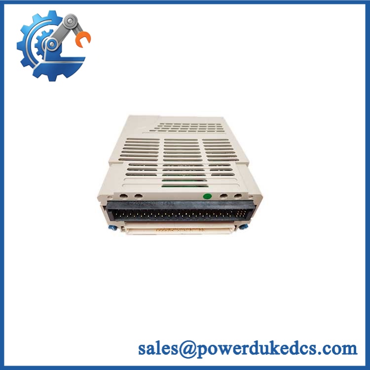
Emerson 1000554
Quality Assurance SOP
For New Surplus Emerson 1000554 inventory, the pre-shipment procedure should include:
- OEM anti-counterfeit visual inspection — inspect Emerson markings, board identification, PCB construction, component population, connector style, labels, and revision codes.
- Physical-condition inspection — check the PCB for corrosion, oxidation, cracked solder joints, damaged connectors, burnt components, and evidence of unauthorized rework.
- Part-number verification — confirm the physical marking reads 1000554 and record all supplementary revision or assembly numbers.
- Power-on self-test (POST) — where a compatible test fixture is available, energize the board and inspect expected status behavior, including any GROUND FAULT or DIODE FAULT indication.
- 24V input verification — confirm the board receives the specified test voltage and inspect the supply path for abnormal current draw or voltage drop.
- Fault-circuit verification — test the applicable ground-fault and diode-fault detection circuitry using the approved test fixture or documented electrical procedure.
- Communication handshake verification — where the host assembly provides a communication or diagnostic interface, verify expected status exchange with the associated control hardware.
- Connector and continuity check — verify relevant connector pins and accessible circuit paths against the applicable wiring documentation.
- Test record and photography — document board markings, revision, physical condition, and final test status before packing.
- ESD-controlled packing — place the PCB in ESD-safe packaging with protection around connectors and exposed components.



 Start Chat


