

Description
- Brand: Emerson
- Full Model Number: CSI3125 A3125/022-020
- Lifecycle Status: Legacy / Current Lifecycle Status to Be Verified
- Core Function: Dual-Channel Bearing-Vibration Monitor
- Top 3 Technical Specs: ICP Piezo-Electric Sensors | 100 mV/in/s Velocity Input | 0/4–20 mA Outputs
- Measurement Application: Absolute Bearing Vibration
- Frequency Range: High-Pass 5–5000 Hz | Low-Pass 50–5000 Hz
- Supply Voltage: 24 VDC Nominal | 18–31.2 VDC Permissible
- Power Consumption: Max. 6 W
- Buffered Outputs: 2 × ±4.0 VDC | ±2.5% Accuracy
- Current Outputs: 2 × 0/4–20 mA | Galvanically Separated
- Relay Outputs: 5 × Make Contact | 48 VDC Max. | 1 A Max.
- Maximum Current-Output Burden: 500 Ohm
- Enclosure: Aluminum, Non-Corroding | IP65
- Operating Temperature: -20 to 65°C (-4 to 149°F)
- Weight: Approx. 1,300 g
- Mounting: Wall Mount
- Stock & Condition: New Surplus / Tested Refurbished Subject to Availability
- Shipping: Expedited Dispatch Subject to Order Cutoff and Carrier Service
- Warranty: 12-Month Supplier Warranty, Subject to Quoted Terms
Supply Chain & Technical Deep Dive
A failed bearing-vibration monitor can leave a small turbine, compressor, pump, or fan without a dedicated absolute-vibration measurement channel while the mechanical fault itself remains under investigation. Emerson CSI3125 A3125/022-020 is a dual-channel bearing-vibration monitor designed for these lower-channel-count machinery applications. The exact A3125/022-020 variant is specified for vibration velocity at 100 mV/in/s, rather than the A3125/022-010 version used for vibration acceleration. The unit accepts ICP piezo-electric sensors, provides field-configurable measurement settings and alarms, and uses a wall-mounted aluminum enclosure with IP65 sealing.
For maintenance procurement, the important numbers are the signal path and output architecture. CSI3125 operates from +24 VDC nominal, with a permissible range of +18 to +31.2 VDC, and has a maximum power consumption of 6 W. Two buffered outputs provide ±4.0 VDC with ±2.5% accuracy, while two galvanically separated current outputs support 0/4–20 mA with a maximum burden of 500 Ohm. Five make-contact relay outputs are rated up to 48 VDC, 1 A, and 50 W. The published specification also lists a high-pass filter range of 5–5000 Hz and a low-pass filter range of 50–5000 Hz, with long-term drift limited to 1% of measuring range. For obsolete-stock purchasing, matching the exact suffix matters because the acceleration and velocity variants are not the same measurement configuration.
Migration, Compatibility & Field Traps
Replacement Matrix
| Replacement Type | Assessment | Engineering Requirement |
|---|---|---|
| Drop-in Replacement | Conditional Like-for-Like Replacement | Confirm CSI3125 architecture, exact A3125/022-020 variant, sensor type, wiring, and installed configuration |
| Software Compatible | Configuration Dependent | Verify measurement range, alarm settings, output configuration, and sensor scaling |
| Hardware Modification | Normally Not Required for Exact Replacement | May be required when changing sensor technology, enclosure arrangement, or monitor family |
The most important compatibility check is the measurement variant. A3125/022-020 is the velocity version, specified at 100 mV/in/s, while /022-010 is the acceleration version at 100 mV/g with a 40 g range. Engineers should not substitute between those two part numbers solely because both belong to the CSI3125 family.
Field Traps — Watch Out
Sensor Type Mismatch: The published CSI3125 specification identifies ICP piezo-electric sensors as the sensor input type. Confirm the installed sensor and signal-conditioning arrangement before connecting the replacement.
Velocity vs. Acceleration Configuration: /022-020 is scaled for vibration velocity. If the existing plant documentation, PLC/DCS scaling, alarm thresholds, or historian tags were configured for acceleration, installing the wrong variant can produce incorrect engineering values even though the monitor powers up normally.
Supply Voltage: The specified supply range is +18 to +31.2 VDC. Check the actual cabinet supply before commissioning, especially on long DC cable runs where voltage drop may be significant.
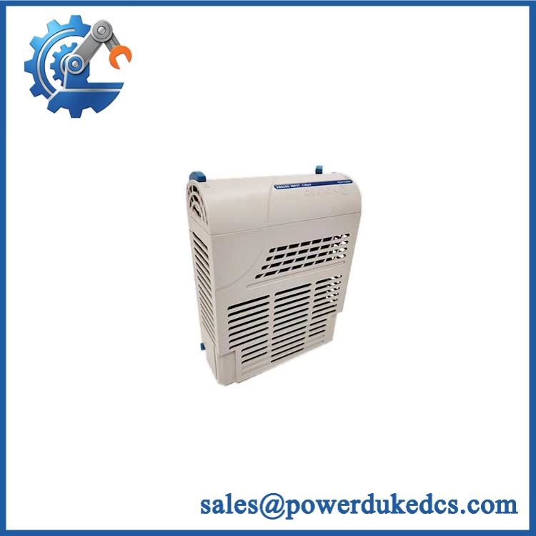
Emerson CSI3125 A3125/022-020
Quality Assurance & Testing SOP
Every Emerson /022-020 unit should undergo a controlled inspection before shipment. Begin with an OEM anti-counterfeit visual inspection covering the Emerson marking, full part number, revision information, enclosure condition, connectors, mounting points, and evidence of unauthorized modification or repair. Record visible identification data before electrical testing.
Power the unit from a controlled 24 VDC source and perform a startup verification. Check supply current, initialization behavior, channel status, and diagnostic response. The permissible supply range of +18 to +31.2 VDC provides the acceptance window for the laboratory power source. Abnormal current draw or unstable startup should stop the test sequence.
Functional testing should use a suitable ICP sensor simulator or calibrated vibration signal source. Both measurement channels are exercised independently. For the /022-020 configuration, verify the velocity signal path using the specified 100 mV/in/s scaling. Check the configurable frequency filters, buffered outputs, isolated 0/4–20 mA outputs, and alarm/relay response where the available test equipment supports those functions.
The test bench should also perform repeated input changes and output-current checks to identify intermittent behavior. Current outputs are tested against the specified range and burden capability, while relay contacts are checked at controlled low-energy loads rather than directly applying maximum rated power during routine inspection. Final QA records should include the exact model number, visible revision, visual inspection result, power-up result, sensor-signal test, analog-output test, relay test, and packaging condition.
Procurement-Driven FAQ
Is Emerson /022-020 genuinely in stock, and what is the cutoff for overnight shipping?
Availability should be confirmed against the exact /022-020 quantity, condition, and revision before purchase-order release. Overnight dispatch depends on warehouse processing time, order cutoff, carrier service, and destination. The confirmed shipment commitment should appear on the quotation.
How do you guarantee the condition of obsolete or surplus units?
The condition should be stated separately from the test result. New Surplus indicates unused inventory, while Tested Refurbished indicates previously used equipment that has completed inspection and functional testing. Buyers should verify the exact model, visible revision, physical condition, and test status before shipment.
What are the warranty terms and return policies for defective units?
Warranty coverage should be defined on the quotation or sales confirmation. Supplier warranty terms may cover verified product defects or dead-on-arrival failures, while damage from incorrect wiring, excessive electrical stress, improper installation, unauthorized modification, or physical damage may be excluded.
Are there any firmware or configuration compatibility issues my engineers should check?
The main engineering concern is measurement configuration, not simply power-up compatibility. Verify the /022-020 velocity configuration, sensor type, scaling, frequency-filter settings, alarm thresholds, and output configuration before commissioning. measurement settings, alarms, and outputs are field configurable through software.
What is the difference between /022-020 and /022-010?
Both are bearing-vibration monitor variants, but their primary measurement scaling differs. /022-020 is specified for vibration velocity at 100 mV/in/s, while /022-010 is specified for vibration acceleration at 100 mV/g with a 40 g range. Use the variant that matches the existing sensor and plant measurement design.



 Start Chat


