

Description
- Model: GE 269PLUS-D/O-261-100P-120
- Brand: GE Multilin
- Series: 269 Plus Motor Management Relay
- Part Type: Drawout motor management and protection relay
- Core Function: Monitors and protects three-phase AC motors using phase-current, ground-fault, RTD, overload, unbalance, and related protection functions.
- Key Specs: Drawout construction; 120 VAC / 125 VDC control power; 100 Ω platinum RTD option; RS485/Modbus-compatible communications; 4 output relay sets; programmable 4–20 mA analog output; maximum control-power consumption of 20 VA.
Product Introduction
A motor can continue drawing current while its thermal condition deteriorates, a bearing temperature rises, or a ground-fault condition develops. The GE Multilin 269 Plus is designed to combine these measurements into a single motor-management and protection platform, giving the installed control system both protective trip functions and operating data.
The supplied code identifies a drawout 269 Plus configuration with the 100 Ω platinum RTD option and 120 VAC / 125 VDC control power. The relay uses an embedded microcomputer, external EPROM firmware storage, keypad/display operation, and an RS485 interface using a Modbus RTU-compatible protocol (important when integrating legacy motor protection into an existing PLC or DCS network).
Core Technical Specifications
| Parameter | Value |
|---|---|
| Manufacturer | GE Multilin |
| Exact Model | 269PLUS-D/O-261-100P-120 |
| Product Family | 269 Plus Motor Management Relay |
| Construction | Drawout |
| Motor Application | Three-phase AC motor protection and management |
| Control Power | 90–300 VDC / 80–265 VAC for the HI range |
| Application-Specific Nominal Supply | 120 VAC / 125 VDC |
| Maximum Control Power | 20 VA |
| Typical Control Power | Approximately 10 VA |
| RTD Option | 100 Ω Platinum RTD |
| RTD Inputs | 10 total |
| RTD Measurement Range | 0–200°C |
| RTD Display Accuracy | ±2°C |
| RTD Dead Band | 3°C |
| Phase Current Measurement | Calibrated RMS, 2 ms sampling |
| Phase Current Range | 0.05–12 × phase CT primary amp setpoint |
| Phase Current Accuracy | ±0.5% FS up to 2 × setpoint; ±1.0% FS above 2 × |
| Ground-Fault Measurement | Calibrated RMS |
| Digital Inputs | Speed switch, differential relay, spare input and related control inputs |
| Output Relays | 4 sets of NO/NC contacts |
| Contact Material | Silver alloy |
| Analog Output | Programmable current output, including 4–20 mA |
| Serial Communications | RS485 |
| Protocol | GE Multilin 269 Plus / Modbus RTU-compatible |
| Communication Distance | Up to 4,000 ft with specified shielded twisted pair arrangement |
| Firmware Architecture | 80C32 microcomputer + external EPROM |
| Display | 2-row × 24-character display |
| Keypad | 12-key |
| Approx. Shipping Dimensions | 7.5 × 11.5 × 5.0 in |
| Approx. Shipping Weight | 6.5 lb / 2.9 kg |
| Country of Manufacture Listed by Supplier | Canada |
| Lifecycle | Legacy / discontinued product family |
The GE instruction manual specifies the 90–300 VDC or 70–265 VAC control-power family range, with maximum consumption of 20 VA and approximately 100 ms typical power holdup at 120 VAC/125 VDC. The RTD section specifies 10 RTD inputs, four supported sensor types, a 0–200°C range, ±2°C display accuracy, and a 3°C dead band.
For the exact requested commercial variant, current distributor records specify 120 VAC / 125 VDC, 100 Ω platinum RTD, 2.9 kg shipping weight, and 7.5 × 11.5 × 5.0 in shipping dimensions.
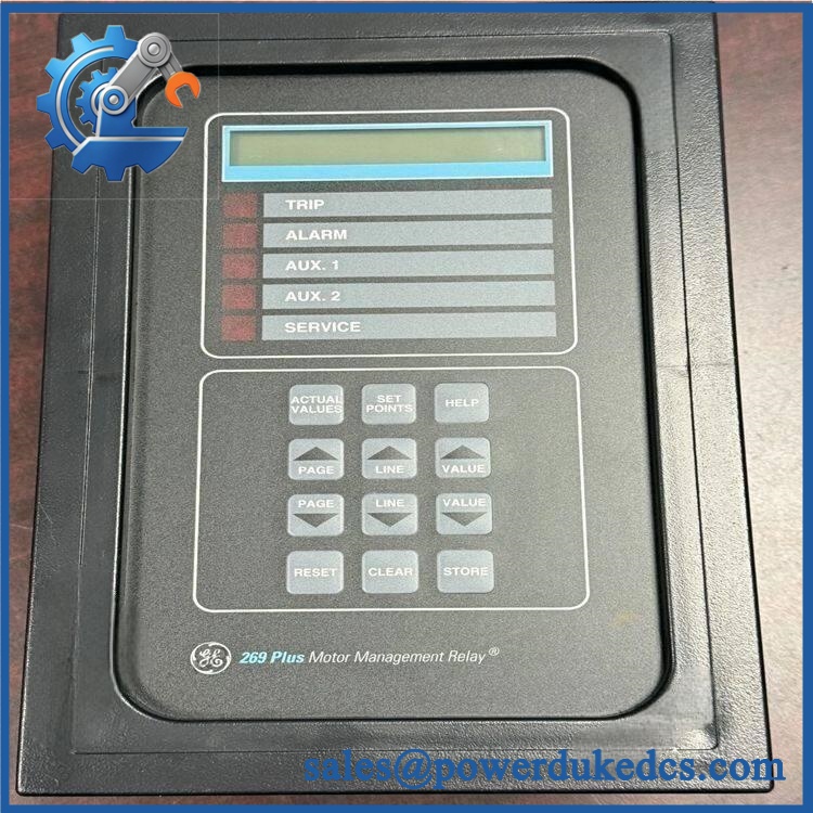
GE 269PLUS-D/O-261-100P-120
Application Scenarios & Pain Points
A large pump motor begins showing elevated bearing temperature while phase current remains normal. With the 269 Plus configured for RTD monitoring, temperature information can be incorporated into the motor protection scheme instead of relying solely on current-based protection. The relay provides 10 RTD inputs, with up to six available for stator-related protection and additional inputs for other temperatures.
In petrochemical and process plants, the relay can monitor overload, unbalance, short-circuit, ground fault, undercurrent, mechanical jam, RTD, and related motor conditions. A plant operating with 50°C+ ambient conditions should still evaluate the actual enclosure thermal environment separately from the relay’s specified operating limits.
For legacy PLC or DCS integration, RS485 communications allow multiple 269 Plus relays to share a communication link. GE specifies a maximum of 32 269 Plus slave devices on one master link, with distinct slave addresses required for each relay.
Within pump and compressor packages, the 269 Plus can provide both protective relay outputs and a programmable analog signal. The analog output can represent parameters such as motor load, thermal memory, maximum stator RTD temperature, bearing RTD temperature, or CT secondary current.
🚨 Common Error Codes & Diagnostic Symptoms
Symptom/Code: A/D H/W FAIL / SELF TEST ALARM → Diagnosis: The relay’s internal self-test has detected a problem in the analog-to-digital conversion circuitry; GE’s troubleshooting table directs the unit to service rather than field adjustment. → Action: Remove the relay from service and replace or professionally repair the unit.
Symptom/Code: RTD H/W FAIL. RTDs OFF → Diagnosis: The internal RTD measurement circuit has failed, causing the relay to disable RTD-related operation. This is different from a simple open field RTD, which produces the separate BROKEN RTD LINE condition. → Action: Verify the field RTD wiring first; if the internal hardware fault remains, replace the relay.
Symptom/Code: METER FAILURE (COMMUNICATION) → Diagnosis: The relay is reporting a communication-related metering failure. Check the RS485 physical layer, addressing, grounding, termination, and master connection before condemning the relay. → Action: Correct the communication path; replace the relay if the internal communication hardware is confirmed defective.
🚨 Cross-Reference & Lifecycle Migration
The 269 Plus ordering structure is highly configuration-specific. The GE manual states that options such as control voltage, RTD type, CT arrangement, failsafe codes, and drawout contact configuration are specified at order time, with some parameters not field-selectable.
For the requested 269PLUS-D/O-261-100P-120, current product records identify it as a drawout version, with 261 relay-option coding, 100 Ω platinum RTD, and 120 VAC / 125 VDC control power. Do not treat the generic 269 Plus family number as sufficient interchangeability information.
The GE manual documents the broader 269/269 Plus family with standard and drawout versions, several CT configurations, four relay-failsafe patterns, contact-arrangement options, and multiple RTD/control-power selections. Consequently, a different suffix can represent a materially different field configuration even when the front panel looks similar.
Firmware: Firmware is real and relevant on this relay. GE states that the firmware is stored in an external EPROM and identifies the installed firmware revision within the relay information menu. Therefore, do not assume that two relays with the same broad 269 Plus family designation have identical firmware contents.
Lifecycle status: The 269 Plus is a legacy platform. Current market records still show specialist inventory and repair availability for the requested drawout configuration, while the product is treated by suppliers as legacy equipment.
For buffer-stock planning, retain the exact ordering code and firmware information together. A family-level spare without verified option coding can create a commissioning problem even when the chassis and display appear identical.
Field Engineer’s Tech Notes
Warning 1 — Do not inject voltage into the digital switch inputs.
GE explicitly warns that these inputs are designed for dry contacts only. Applying an external voltage to a dry-contact input can damage the input circuitry and create a second fault during what should have been a simple replacement.
Warning 2 — RS485 grounding and termination are not optional details.
GE specifies shielded twisted-pair wiring, a single master, unique slave addresses, and proper termination at the two ends of the network. The manual also warns that significant ground-potential differences can prevent communication. Check the communication reference and ground arrangement before blaming the relay (this is a frequent legacy-panel diagnostic trap).
Strict QA & Testing SOP
Step 1 — Identity inspection
Confirm 269PLUS-D/O-261-100P-120, serial number, hardware revision, nameplate markings, RTD option, and control-power marking. Photograph the complete nameplate before unpacking.
Step 2 — Mechanical inspection
Inspect the drawout housing, front display, keypad, rear terminal area, extraction mechanism, terminal screws, connector pins, and enclosure for impact or corrosion.
Step 3 — Internal condition check
Where inspection is authorized, check for contamination, damaged wiring, cracked components, overheated areas, and evidence of previous unauthorized repair. Do not alter factory calibration adjustments.
Step 4 — Power-up test
Apply the correct control voltage through a protected test supply. The GE manual specifies a high-range control-power capability of 90–300 VDC or 70–265 VAC, depending on the relevant configuration. Record startup behavior and any self-test alarms.
Step 5 — Display and keypad verification
Confirm the 2 × 24-character display, all front-panel indicators, and keypad response. Verify that the relay information screen can report the firmware revision and serial number.
Step 6 — RTD simulation
Use suitable resistance simulators or calibrated RTD sources to check the configured 100 Ω platinum RTD channels. Verify expected temperature indication and alarm/trip behavior without altering protected production settings. The documented RTD range is 0–200°C.
Step 7 — Current-input testing
Inject controlled phase-current and ground-fault signals within the test procedure. Confirm RMS measurement response, phase-current scaling, and protection thresholds.
Step 8 — Output relay test
Verify Trip, Alarm, Aux1, and Aux2 contacts against the specified failsafe and contact arrangement. The GE manual identifies Form C NO/NC contact configurations and silver-alloy contacts.
Step 9 — Communications test
Connect the interface to an approved Modbus/269 Plus test master. Confirm addressing, register read/write behavior, termination, and stable communication over the intended baud/configuration. GE documents the 269 Plus protocol as Modbus RTU-compatible.
Step 10 — Final packaging
After passing QA, protect the relay in ESD-safe packaging, cushion the drawout assembly against shock, and record the test configuration. Test videos are available for qualifying inventory when pre-shipment evidence is required.
Buyer’s FAQ
Q1. Can I hot-swap the 269PLUS-D/O-261-100P-120?
Do not assume unrestricted live replacement. This is a drawout protective relay, and removing or inserting it can affect protection, CT circuits, control wiring, and breaker/motor operating conditions. Follow the site’s switching procedure and the equipment-specific GE instructions before withdrawal.
CT circuits require particular care. Never open-circuit an energized CT secondary merely to remove a relay.
Q2. How do I verify that a New Original unit is actually the requested configuration?
Check the full nameplate code, not just “269 Plus.” Confirm the D/O designation, 261 option code, 100P RTD selection, and 120 control-power designation against the purchase order and installed relay. Current supplier records identify the exact requested configuration with these parameters.
For higher-value procurement, retain photographs of the nameplate, serial number, front panel, rear terminals, packaging, and firmware screen.
Q3. What warranty should be specified on the purchase order?
Warranty terms vary with inventory condition and supplier. One current supplier listing for this exact configuration states a 2-year warranty for surplus parts and repairs. That is a supplier-specific commercial term, not a universal GE warranty.
For procurement control, specify whether warranty coverage applies to new original, new surplus, repaired, or refurbished condition and whether failures caused by incorrect installation are excluded.
Q4. What firmware should the replacement contain?
The relay has actual firmware stored in external EPROM, and the installed firmware revision can be viewed from the relay information menu.
For an installed-base replacement, request the firmware revision, hardware revision, and complete ordering code before shipment. Matching only the 269 Plus family name is not enough where the existing motor protection settings, communications integration, or option configuration depend on the installed revision.
Procurement Note
For GE 269PLUS-D/O-261-100P-120, the critical receiving fields are the complete ordering code, serial number, hardware revision, firmware revision, RTD type, control-power marking, drawout configuration, contact arrangement, certification markings, COO, and actual test status. The exact commercial variant is more important than the generic “269 Plus” description.











 Start Chat


