

Description
- Brand: GE Multilin
- Full Model Number: 339-E-P5-G5-H-E-S-N-N-SN-D-N
- Short Model: 339-EP5G5HESNNSNDN
- System/Series Family: Multilin 339 Motor Protection System
- Core Function: Microprocessor-based protection and control for three-phase industrial motors
- Top 3 Hardcore Specs: 5 A phase current inputs | 5 A ground current input | 110–250 VDC / 110–230 VAC power supply
- Contact Inputs: 10
- Outputs: 2 Form A + 5 Form C
- Case Type: Drawout
- Communications: USB + RS-485 serial interface
- Stock Status: New surplus, factory sealed, or fully tested refurbished subject to current inventory confirmation
The exact 339-E-P5-G5-H-E-S-N-N-SN-D-N configuration is documented as a GE Multilin 339 Motor Protection System relay. Available technical records identify 5 A three-phase current inputs, a 5 A ground-current input, 10 contact inputs, and seven relay outputs consisting of two Form A and five Form C contacts.
Module 3: Technical Product Introduction
When a medium-voltage motor trips repeatedly or loses its protection relay, replacing the relay with the wrong option code can create a second commissioning problem. The GE Multilin 339-E-P5-G5-H-E-S-N-N-SN-D-N is a specific 339-series configuration for motor protection, with 5 A phase-current and 5 A ground-current inputs. Its drawout construction also allows the relay assembly to be withdrawn from its case during maintenance, which can reduce the physical work required compared with a fixed installation.
The electrical configuration is equally important. Published records specify a 110–250 VDC / 110–230 VAC control-power range, 10 contact inputs, and 7 outputs configured as 2 Form A plus 5 Form C. The unit also provides USB and RS-485 interfaces. These figures describe the exact listed configuration; they should not be generalized to every 339 relay, since the 339 family uses option-code combinations to define different hardware and feature sets.
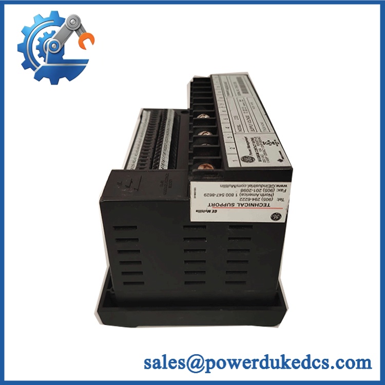
GE 339-E-P5-G5-H-E-S-N-N-SN-D-N
Module 4: Application Scenarios & Field Realities
- On medium-voltage motor feeders, the 339 is intended to supervise motor electrical conditions and initiate protective action when configured thresholds are exceeded. During troubleshooting, compare relay event records with measured phase and ground-current values before replacing the hardware.
- For motors using 5 A CT secondaries, this exact configuration is relevant because both the three-phase current inputs and ground-current input are listed at 5 A. CT secondary rating must be confirmed before energization; never assume a 1 A and 5 A relay input are interchangeable.
- During an outage, the drawout case can simplify relay removal and replacement. Before withdrawing the relay, document the existing settings, CT connections, control wiring, communication configuration, and front-panel diagnostic state.
- Where the relay communicates with a plant monitoring system, the available USB and RS-485 interfaces provide local and serial communication paths. Record the existing communication parameters before replacement; restoring the protection function is only part of the commissioning task.
Module 5: Migration, Compatibility & Installation Traps
Replacement Matrix
| Replacement Type | Assessment | Engineering Requirement |
|---|---|---|
| Drop-in Replacement | Yes, for an exact 339-E-P5-G5-H-E-S-N-N-SN-D-N configuration | Match complete option code, CT ratings, control power, I/O, case arrangement, and settings |
| Software Compatible | Configuration-dependent | Verify protection settings, firmware, communication parameters, and stored application data |
| Hardware Modification Required | Not normally required for an exact same-configuration replacement | Confirm the existing drawout case and wiring before installation |
Field Traps — Watch Out
1. Option-code mismatch: The long GE model number is not decorative. The P5 and G5 portions identify important current-input configurations, while the H power-supply option corresponds to the high-voltage control-power range documented for this unit. Do not substitute another 339 model simply because its front panel and enclosure appear identical.
2. CT secondary mismatch: This configuration is listed with 5 A phase-current and 5 A ground-current inputs. A relay configured for a different CT secondary rating can produce incorrect measurements and protection behavior. Verify every CT circuit before inserting the replacement.
3. Protection settings are part of the replacement: A physically compatible relay is not automatically a commissioned relay. Record motor FLA, overload class, short-circuit protection, ground-fault settings, start-related parameters, trip outputs, and communication settings before removing the original unit.
4. Drawout handling: Isolate the relevant control and protection circuits according to the site’s switching procedure before withdrawing the relay. Never treat the drawout mechanism as authorization to remove the relay while energized.
Module 6: Quality Assurance SOP
Before shipment, each GE Multilin 339-E-P5-G5-H-E-S-N-N-SN-D-N should pass a documented inspection sequence appropriate to the available protection-relay test equipment.
- Step 1 — Part-number verification: Record the complete 339-E-P5-G5-H-E-S-N-N-SN-D-N designation, serial number, firmware information where accessible, and all visible GE/Multilin identification markings.
- Step 2 — OEM anti-counterfeit visual inspection: Inspect the front panel, labels, display, terminal blocks, connectors, enclosure, PCB markings, fasteners, and manufacturing identifiers. Photograph the complete nameplate and model code.
- Step 3 — Physical condition inspection: Check the drawout mechanism, terminal connections, housing, display, keypad, communication ports, and PCB assembly for impact damage, corrosion, contamination, cracked components, or evidence of unauthorized repair.
- Step 4 — Control-power verification: Confirm that the test supply matches the documented 110–250 VDC / 110–230 VAC input range before energizing the relay.
- Step 5 — Power-on self-test (POST): Energize the relay under controlled conditions and record startup behavior, display operation, diagnostic status, and available ERR/RUN or equivalent indications.
- Step 6 — Current-input verification: Using an appropriate relay test set, inject representative 5 A-class phase and ground-current signals and verify measurement response against the expected values.
- Step 7 — Digital I/O verification: Exercise representative contact inputs and relay outputs. Confirm the expected operation of the 2 Form A and 5 Form C output contacts where the test fixture supports these checks.
- Step 8 — Communication handshake verification: Test the applicable USB or RS-485 communication interface and confirm that the relay can establish the expected local or serial connection.
- Step 9 — Protection-function verification: Where a calibrated relay test system is available, verify selected protection elements against documented test points. Record pickup, timing, and output operation rather than relying solely on a successful power-up.
- Step 10 — Final photographic record: Photograph the relay, model label, serial information, connectors, front-panel condition, and final packaging before shipment.
QA release criterion: The relay should not be described as fully function-tested unless current injection, I/O, communication, and relevant protection functions were actually verified. A successful power-up confirms basic operation; it does not by itself prove protection accuracy.











 Start Chat


