

Description
- Model: GE 369-C100
- Brand: GE / GE Multilin
- Series: Multilin 369 Motor Management Relay
- Part Type: Upper Control Board / PCB
- Core Function: Provides the principal control electronics within the Multilin 369 relay assembly; it should be treated as an internal replacement board rather than a complete 369 relay.
- Key Identification: Public parts records cross-reference 369-C100 with 1253-0002-C2 and identify it as the Multilin Upper Control Board.
- Critical Asset Note: Do not confuse this board with the complete 369 relay or with 369-C101, which is listed separately as the Lower Control Board.
Product Introduction
A plant can have a perfectly serviceable motor-protection installation and still be forced into an urgent repair when the upper control electronics inside a legacy 369 relay fail. The GE 369-C100 is identified in secondary parts records as the Upper Control Board, with 1253-0002-C2 given as the associated board number. It belongs to the GE Multilin 369 motor-management platform rather than representing a standalone modern PLC module.
The underlying 369 relay provides three-phase motor protection and management, including overload, short-circuit, ground-fault, mechanical-jam, and other protection functions. The platform also supports a front RS-232 interface, three rear RS-485 ports, Modbus RTU, optional RTD inputs, and optional communications interfaces.
For procurement, the board-level identity is the key point. A 369-C100 / 1253-0002-C2 should not be purchased on the assumption that it is interchangeable with a complete 369 relay, a 369-C101 lower board, or another internal PCB revision. Public listings clearly distinguish the upper and lower control assemblies.
Core Technical Specifications
| Parameter | Value |
|---|---|
| Manufacturer | GE / GE Multilin |
| Model | 369-C100 |
| Associated Board Number | 1253-0002-C2 |
| Product Family | Multilin 369 |
| Hardware Type | Upper Control Board / PCB |
| Parent Equipment | GE Multilin 369 Motor Management Relay |
| Primary Function | Relay control and processing electronics |
| Relay Architecture | Microprocessor-based motor protection and management |
| CPU / Processing Detail | Exact processor specification for 1253-0002-C2 not reliably established in public documentation |
| Board Memory | Parent 369 platform uses flash memory; exact C100 board memory allocation is revision-dependent |
| Standard Communications of Parent Relay | 1 × RS-232 front port; 3 × RS-485 rear ports |
| Standard Protocol | Modbus RTU |
| Optional Communications | Modbus/TCP, Profibus-DP/DPV1, DeviceNet, fiber optic, according to ordered relay configuration |
| Parent Relay Control Power — HI | 50–300 VDC / 60–265 VAC |
| Parent Relay Control Power — LO | 20–60 VDC / 20–48 VAC |
| Parent Relay Maximum Power | Approximately 35 VA typical / 75 VA maximum for the documented relay specification |
| Relay Firmware History | Documented revisions from the original production release through at least 53CMC340.000 |
| Installation | Internal assembly within a Multilin 369 relay |
| Complete Relay Dimensions | Approx. 251 × 190 × 156 mm for the 369 enclosure |
| Board Dimensions | Exact PCB dimensions not reliably published |
| Board Weight | Exact OEM weight not reliably published |
| Battery | Not confirmed for this specific upper board |
| Lifecycle | Legacy; 369 manufacturing discontinued |
The 369 platform documentation gives the control-power ranges, communications architecture, flash-memory capability, and extensive firmware history. Importantly, the firmware belongs to the complete 369 relay platform, not necessarily to a separately serialized upper PCB.
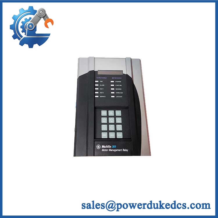
GE 369-C100
Application Scenarios & Pain Points
Micro-case — motor starter protection: A medium-voltage motor remains mechanically healthy, but the installed 369 relay begins losing its control display or fails self-diagnostics. When troubleshooting establishes a board-level fault, an exact upper-control replacement can preserve the existing protection architecture while avoiding an immediate whole-relay changeout.
For chemical and process plants, the 369 can provide overload, short-circuit, ground-fault, mechanical-jam, and temperature-related protection depending on the ordered configuration. The parent relay supports up to 12 RTD inputs on the appropriate option.
Within water and wastewater facilities, legacy 369 relays may remain tied to established starter wiring and SCADA communications. GE’s current 859 platform is specifically positioned as a successor to the 369, and GE states that the 859 can retain the same cutout and terminal arrangement for 369 replacement projects.
At high-temperature installations approaching 60°C, thermal inspection becomes important because the documented 369 production-test regime included 8 hours at 60°C during sampling burn-in. That test condition should not be mistaken for a blanket recommendation to operate every installation continuously at 60°C.
With vs. without the spare: retaining an exact board can shorten diagnosis and restoration when the surrounding 369 wiring, settings, and communications infrastructure are still serviceable; without board-level stock, the maintenance team may need to source a complete legacy relay or begin a larger migration exercise.
🚨 Common Error Codes & Diagnostic Symptoms
The available 369 documentation emphasizes displayed causes, self-diagnostics, alarms, trips, and the SERVICE LED rather than a universal -specific numerical fault-code table. Therefore, board-level symptoms should not be mislabeled as official 369- error codes.
Symptom: SERVICE LED remains active / self-diagnostic failure → Diagnosis: The 369 documentation states that the SERVICE indication can represent a failed self-diagnostic test or Test Mode. Where configuration and external wiring have been eliminated as causes, an internal control-board fault becomes a replacement candidate → Action: Isolate the relay, inspect the upper-control assembly, and replace the only after board-level verification.
Symptom: Display or keypad becomes unavailable while control power is confirmed → Diagnosis: The front panel belongs to the complete 369 assembly, and loss of normal processor/display operation with confirmed control power can indicate an internal electronics fault → Action: Verify power supply and connectors first; substitute a known-good upper control board when evidence points to the .
Symptom: Relay repeatedly fails to communicate over RS-232/RS-485 → Diagnosis: Communications problems can originate in wiring, settings, external protocol modules, or the internal controller; the 369 supports one front RS-232 port and three independent rear RS-485 ports → Action: Validate cable, address, baud rate, and protocol first; replace the upper board only when internal communication hardware is implicated.
🚨 Cross-Reference & Lifecycle Migration
Board Cross-Reference
GE 369- → 1253-0002-C2 → Multilin Upper Control Board.
This cross-reference is supported by current secondary parts records and should be retained in the purchasing master.
Do not confuse it with:
- 369-C101 / 1753-0005: documented as the Lower Control Board.
- 369-A200 / 1253-0003-series: associated with the analog/I/O board rather than the upper control board.
- Complete 369 relay: the is an internal board, not the complete field-mounted relay.
Firmware Compatibility
The 369 platform has a substantial firmware history. GE’s documentation records revisions from 53CMB110.000 through 53CMC340.000, with later versions adding features such as Modbus/TCP, DeviceNet, Profibus-DPV1, data logging, and communications-loss functions.
A board replacement should therefore not be treated as firmware-neutral without checking the actual relay revision. GE documentation also states that the firmware shown on the relay label is the factory-installed version and that the currently installed firmware should be checked in the relay’s actual-values section.
Lifecycle Status
Lifecycle: Legacy / Manufacturing Discontinued.
GE Vernova currently lists the Multilin 369 as a Legacy product and states that manufacturing has been discontinued, with the Multilin 859 positioned as a successor.
For buffer-stock strategy, that changes the calculation. A 369- is no longer ordinary replenishment inventory; for a plant with multiple installed 369 relays, retaining at least one verified board or complete relay assembly for critical applications can reduce exposure to long sourcing cycles while a controlled migration plan is developed.
Field Engineer’s Tech Notes
First warning: do not power the board from an assumed relay rating. The 369 family has both HI and LO control-power versions, so the complete relay configuration must be established before any powered diagnostic procedure. The board itself should not be used as evidence of the required control-voltage class.
Second warning: never treat and C101 as interchangeable. Public parts records identify as the upper control board and C101 as the lower control board. Before removing a board, photograph every connector and board-level marking (especially the assembly number and revision); legacy relay cabinets often contain decades-old modifications that are not obvious from the standard drawing.
Use ESD protection whenever the PCB is outside the relay housing. Avoid touching the edge contacts or component pins unnecessarily.
Strict QA & Testing SOP
1. Inbound identity check
Confirm and the associated 1253-0002-C2 marking where present. Photograph the board label, PCB revision, serial/date information, connectors, and any factory stickers.
2. Physical inspection
Check the PCB for cracked solder joints, lifted components, corrosion, contamination, overheated areas, damaged connectors, or evidence of previous rework. Particular attention should go to connector headers and mechanically stressed mounting points.
3. Revision and traceability check
Record all board-level markings. Do not erase, replace, or obscure original identification labels during cleaning.
4. Controlled electrical inspection
Check for obvious shorts between applicable supply and ground points before applying power. Use the approved 369 service documentation for any resistance or voltage test limits; do not invent board-level acceptance thresholds from the complete-relay specification.
5. Live relay-rig test
Install the board into a compatible test assembly or verified 369 relay chassis. Confirm processor startup, display/keypad operation, self-diagnostics, communications, and representative relay functions.
6. Communications test
Verify the applicable RS-232/RS-485 communication channel and, where the parent relay is equipped accordingly, test the configured protocol interface. Compare settings with the customer’s installed relay configuration.
7. Functional verification
Where appropriate, test representative protection, metering, alarm, and relay-output functions. The original GE production documentation records 100% hardware-function testing and calibration for the complete relay, together with dielectric testing and an 8-hour burn-in sampling regime.
8. Final preservation
Place the approved board in an ESD shielding bag, add mechanical cushioning, and attach the QC identification record. Keep the original board number and revision visible.
Test videos are available when live-rig verification is performed and the buyer requires visual evidence of the inspection.
Buyer’s FAQ
Is GE 369- a complete Multilin 369 relay?
No. The available parts records identify 369- as the Multilin Upper Control Board, associated with 1253-0002-C2. It should therefore be purchased and documented as an internal PCB unless the supplier explicitly offers a complete assembled relay.
Can I install in place of C101?
Do not do that. is identified as the Upper Control Board, while is identified as the Lower Control Board. They are different assemblies with different functions.
Is hot-swapping the safe?
Do not remove or insert the board under power unless the applicable GE service procedure for the exact 369 assembly explicitly permits it. The 369 relay can operate from potentially hazardous AC/DC control-power ranges, including up to 300 VDC / 265 VAC on the HI version. De-energize the panel and follow site electrical-safety procedures before board removal.
How do I verify New Original authenticity and warranty?
For a claimed New Original , request photographs of the actual PCB, GE/Multilin identification labels, assembly number 1253-0002-C2 where applicable, and packaging labels before shipment. For warranty control, record the board revision, serial/date code, condition classification, test record, and warranty period on the purchase document.
The complete 369 platform is now a discontinued legacy product, so traceability is particularly important when comparing an unused original board with repaired or remanufactured stock. GE Vernova currently identifies the 369 as discontinued and points users toward the 859 for replacement projects.











 Start Chat


