

Description
- Model: GE 369-HI-0-M-0-E-0
- Brand: GE Multilin
- Series: 369 Motor Management Relay
- Part Type: Digital motor protection and management relay
- Core Function: Provides protection, measurement, control, event recording, and communications for three-phase AC motors.
- Configuration Indication:
HIdenotes high-range control power;0indicates no optional RTD inputs;Mindicates the metering package;0indicates no fiber-optic option;Edenotes the optional Modbus/TCP interface; the trailing configuration field requires confirmation against the physical nameplate. - Key Specs: 50–300 VDC / 60–265 VAC control power, six optically isolated digital inputs, 1 A or 5 A CT secondaries, three RS485 channels, one standard analog output, and additional metering outputs with the M option.
Product Introduction
A medium- or large-size motor does not fail only through an obvious overload. Phase imbalance, ground fault, locked rotor, mechanical jam, undervoltage, and abnormal thermal behavior can all develop under operating conditions where a basic overload relay provides limited information. The GE Multilin 369 combines these protective functions with electrical metering and programmable control logic.
For the configuration represented by the supplied code, the M metering option is the important distinction: the 369 can measure voltage, current, power, reactive power, apparent power, power factor, frequency, and energy. The E communications field in documented ordering structures represents the optional Modbus/TCP protocol interface. No optional RTD inputs are indicated by the 0 RTD field.
Core Technical Specifications
| Parameter | Value |
|---|---|
| Manufacturer | GE Multilin |
| Product Family | Multilin 369 Motor Management Relay |
| Supplied Model | 369-HI-0-M-0-E-0 |
| Verified Related Ordering Variants | 369-HI-0-M-0-E-0-E / 369-HI-0-M-0-0-E-0 |
| Relay Type | Digital motor management and protection relay |
| Motor Application | Three-phase AC motors |
| Control Power | 50–300 VDC / 60–265 VAC |
| RTD Option | 0 — no optional 12-channel RTD package |
| Metering Package | M — included |
| Fiber Optic Port | 0 — not installed |
| Communications Option | E — Modbus/TCP interface in the documented ordering structure |
| Harsh Environment Option | 0 — standard environment |
| Enhanced Diagnostics | Configuration-dependent; final ordering-code field must be confirmed |
| Digital/Switch Inputs | 6 optically isolated |
| Phase CT Inputs | 1 A or 5 A secondary |
| Ground CT Inputs | 1 A, 5 A, and sensitive ground-CT options depending on configuration |
| Voltage Inputs | 0–240 V range with Wye or Delta VT connections |
| Analog Outputs | 1 base output; metering/backspin options provide additional outputs |
| Communications | RS232 programming; RS485 serial interfaces; optional Modbus/TCP for E configuration |
| Display | 40-character LCD |
| User Interface | Front-panel keypad |
| Status Indicators | 10 LED indicators |
| Control Power Consumption | Approximately 20 VA nominal; up to 65 VA maximum in published data |
| Internal Fuse | 3.15 A, 250 V slow-blow |
| Operating Temperature | Approximately 5°C to 60°C for documented HI configurations |
| Storage Temperature | Approximately -40°C to 80°C for documented variants |
| Humidity | Up to 95% RH, non-condensing |
| Maximum Altitude | 2,000 m |
| Approx. Dimensions | 296 × 107 × 205 mm |
| Approx. Weight | Approximately 4.5 kg |
| Mounting | Panel-mounted, non-drawout |
The GE manual specifies the basic ordering architecture, the HI control-power range, six optically isolated switch inputs, current and voltage inputs, communications options, metering functions, and the non-drawout mechanical design.
The 369 is not a drawout relay. That point is worth retaining in the warehouse master data because several legacy motor-relay families use physically different withdrawal arrangements.
Power and Thermal Note
Published technical records give approximately 20 VA nominal and 65 VA maximum control-power consumption. Use the actual relay configuration when calculating cabinet loading, because auxiliary options can change electrical demand.
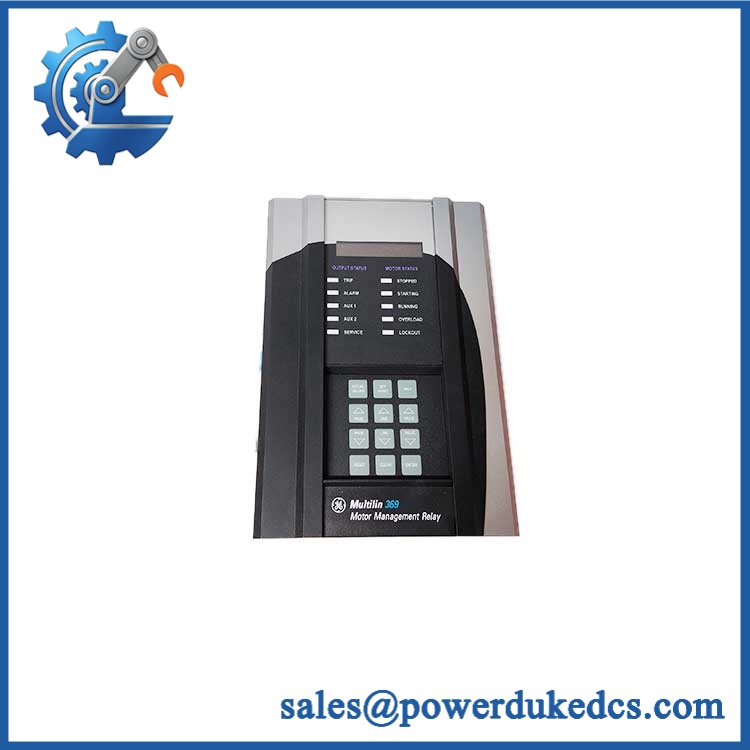
GE 369-HI-0-M-0-E-0
Application Scenarios & Pain Points
A process-pump motor begins tripping during acceleration rather than at steady state. The 369 provides motor-learning and protection parameters associated with inrush current, acceleration behavior, cooling characteristics, overload, stall, and jam conditions. This gives maintenance personnel more diagnostic information than a simple thermal overload device.
In refinery and petrochemical motor centers, the metering option provides electrical values such as voltage, current, power, power factor, frequency, and energy. Those values can be brought into the plant monitoring layer when the communications option is properly configured.
For large compressor or fan motors, current-based protection can be supplemented with phase-loss, current-unbalance, undercurrent, ground-fault, stall, and thermal functions. The 369 also supports event recording and oscillographic information for fault investigation.
When legacy PLC integration is required, the optional E interface corresponds to Modbus/TCP in the documented ordering structure. The relay also retains RS232 and RS485 interfaces, which are useful during commissioning and maintenance.
At high ambient temperatures, cabinet design becomes important. A 50°C+ enclosure environment leaves much less thermal margin than a normal room-temperature control room, particularly when several relays are installed together.
🚨 Common Error Codes & Diagnostic Symptoms
Symptom/Code: SERVICE LED active / self-test alarm → Diagnosis: The relay has detected an internal service condition or failed diagnostic check. External wiring should be eliminated as the cause before condemning the electronics. → Action: Review the displayed diagnostic message and relay self-test information; replace the relay if an internal hardware failure is confirmed.
Symptom/Code: Persistent RTD H/W FAIL on an RTD-equipped 369 → Diagnosis: This specifically indicates an internal RTD interface problem, whereas an open sensor or field wiring problem can produce a different diagnostic condition. For the supplied 0 RTD configuration, this function should not be expected. → Action: Confirm the actual nameplate option code before troubleshooting or ordering a replacement.
Symptom/Code: RS485/Modbus communication loss while relay protection remains active → Diagnosis: Check termination, node/address configuration, grounding, baud settings, and the communication interface before replacing the relay. The 369’s protection functions can remain operational while the external communications path has failed. → Action: Isolate the communications fault; replace the relay only after the physical network and configuration have been verified.
🚨 Cross-Reference & Lifecycle Migration
The 369 ordering code is functional, not cosmetic. Each option field controls a real hardware or firmware capability. GE’s documented code structure specifies:
HI= 50–300 VDC / 60–265 VAC control power.0in the second option position = no 12-channel RTD input package.M= metering package.0= no fiber-optic port.E= Modbus/TCP protocol interface.0= no harsh-environment option.- Final
E= enhanced diagnostics and enhanced faceplate.
This creates an important procurement issue with the supplied 369-HI-0-M-0-E-0: the commonly documented full ordering structure contains a final enhanced-diagnostics field, so the exact nameplate should be checked to determine whether the supplied code is abbreviated or whether a final 0/E field has been omitted. Closely matching documented configurations exist in current industrial records.
Firmware: Firmware is field-relevant on the 369. GE documentation states that new firmware can be downloaded through the RS232 programming interface into relay flash memory without changing an EPROM.
Option migration: GE states that options are factory-installed and that field upgrades require the necessary hardware and an option-enabling passcode. Hardware modifications performed in the field can void warranty/support. Therefore, a relay lacking a required hardware option should not be treated as equivalent simply because the software menu looks similar.
Lifecycle status: The Multilin 369 is a legacy motor-management platform with specialist aftermarket availability. Current listings still show multiple 369 configurations, while suppliers categorize some variants as classic or legacy inventory.
For buffer stock, record the complete ordering code, hardware revision, firmware revision, and installed option set. A generic 369 spare is not an adequate substitute for an option-specific unit.
Field Engineer’s Tech Notes
Warning 1 — Ground the relay exactly as specified.
The installation documentation requires both the safety ground and filter ground to be connected correctly to the main ground bus. Do not daisy-chain the protective grounding arrangement through another relay; GE specifically calls for a dedicated grounding connection to the bus.
Warning 2 — Never open-circuit an energized CT secondary.
The 369 uses external phase CT inputs, including 1 A and 5 A secondaries. Confirm the CT circuit is safely handled before withdrawing or disconnecting wiring (a careless open CT secondary can create dangerous voltages).
Strict QA & Testing SOP
Step 1 — Nameplate verification
Record the exact catalog code, serial number, hardware revision, firmware revision, control-power range, and every visible option code. For this supplied code, specifically verify the missing/final ordering-code field.
Step 2 — Mechanical inspection
Check the metallic housing, front keypad, LCD, LED indicators, rear connectors, terminal screws, mounting hardware, and enclosure for impact, corrosion, moisture ingress, or unauthorized modifications.
Step 3 — Internal visual inspection
When permitted, inspect the PCB for overheated components, cracked solder joints, corrosion, contamination, or evidence of repair. Do not disturb calibration components.
Step 4 — Control-power test
Apply a protected test supply within the documented HI range of 50–300 VDC or 60–265 VAC. Record startup behavior and any self-test messages.
Step 5 — User-interface verification
Check the 40-character display, keypad, status LEDs, Trip/Alarm/Aux indications, and service indication. Confirm that actual values and setpoint menus are accessible.
Step 6 — Metering verification
For the M configuration, inject suitable simulated voltage and current signals. Verify voltage, current, power, reactive power, apparent power, power factor, frequency, and energy readings against calibrated references where the test facility supports them.
Step 7 — Digital-input testing
Test the six optically isolated switch inputs using dry-contact simulation. Confirm the relay responds correctly without applying an unauthorized external voltage to the input circuits.
Step 8 — Output-relay testing
Verify Trip, Alarm, Aux1, and Aux2 contact operation against the recorded configuration. Check both contact continuity and programmed operation.
Step 9 — Communications testing
Test RS232 and RS485 functions as applicable. Where the physical unit contains the E communications option, verify the Ethernet interface and Modbus/TCP communication with an approved test system.
Step 10 — Firmware and configuration record
Capture the firmware revision and compare it with the target plant configuration. Retain a copy of the setpoint file when available.
Step 11 — Final preservation
Clean the enclosure externally, protect connectors against contamination, place the relay in appropriate ESD packaging, and use shock-protected packing material.
Test videos are available for qualifying inventory when pre-shipment evidence is required.
Buyer’s FAQ
Q1. Can I hot-swap this 369 relay?
Do not assume that live removal is acceptable. The 369 is a panel-mounted motor protection relay connected to CTs, voltage circuits, control power, outputs, and communication wiring. CT circuits require particular caution before any disconnection. Follow the site’s switching and energized-work procedure.
Q2. How do I confirm that a New Original unit has the same configuration?
Check the complete ordering code on the physical nameplate. Pay particular attention to HI/LO control power, RTD option, M/B option, fiber option, protocol option, harsh-environment option, and enhanced-diagnostics option. GE specifically defines these fields as hardware or feature selections.
For the supplied 369-HI-0-M-0-E-0, I would not approve a replacement until the physical nameplate confirms whether the final enhanced-diagnostics field is omitted by shorthand or represents a specific final option.
Q3. What warranty should be specified?
Warranty is supplier-specific for legacy 369 inventory. Current aftermarket listings show examples of 12-month coverage and 2-year coverage depending on supplier and inventory class. Those commercial terms should not be represented as a universal GE warranty.
For a purchase order, specify the condition—New Original, New Surplus, refurbished, or repaired—and state the warranty period explicitly.
Q4. Does the relay require firmware flashing after replacement?
Not necessarily. GE’s documentation states that firmware can be downloaded through the RS232 programming port into flash memory.
The important requirement is to match the replacement’s hardware options and firmware with the installed application’s setpoint/configuration environment. A firmware revision alone cannot add a hardware option that was never installed at the factory.
Procurement and Lifecycle Note
The GE Multilin 369 remains relevant as a legacy motor-protection spare, but configuration control is critical. The M metering option, communications option, RTD hardware, fiber interface, harsh-environment construction, and enhanced diagnostic hardware are separate ordering selections.
For 369-HI-0-M-0-E-0, retain the exact physical nameplate photograph with the procurement record before purchase approval. This is the safest way to resolve the apparent abbreviated ordering code and prevent a visually similar but functionally different 369 from entering critical spare inventory.











 Start Chat


