

Description
- Model: GE 369B1844G5004
- Brand: GE / GE Vernova
- Series: Nexus / OC 6000e
- Part Type: 16-channel digital output module with AC relay outputs
- Core Function: Provides relay-isolated discrete outputs for turbine-control field devices, switching external AC or DC loads from the Nexus control system.
- Key Specs: 16 dry-contact relay channels; 12 A @ 250 VAC resistive, 12 A @ 30 VDC resistive, 7.5 A @ 250 VAC inductive, and 6 A @ 30 VDC inductive; 24 VDC control interface; 1.3 W typical module consumption.
Product Introduction
The 369B1844G5004 is positioned in the Nexus I/O architecture as the MDO53 16-channel discrete output module with relay output. GE system documentation identifies the exact catalog number and associates it with the MDO53 designation. Each output uses a dry-contact relay, allowing the control system to switch field circuits while maintaining substantial electrical isolation between the module, channels, and system.
For maintenance teams, the relay specification is the first compatibility checkpoint. The module is not simply a generic 24 VDC output card: contact ratings differ according to resistive or inductive loading, and the certified hazardous-area variants use different relay limits. The MDO53-CBACN/CBAUS IECEx variants, for example, are documented separately with lower certified DC relay ratings of 8 A resistive / 4 A inductive at 30 VDC. Do not transfer those limits to the ordinary 369B1844G5004 without checking the exact assembly.
Core Technical Specifications
| Parameter | Value |
|---|---|
| Manufacturer | GE / General Electric |
| GE Item Code | 369B1844G5004 |
| Module Name | MDO53 |
| Product Family | Nexus / OC 6000e |
| Hardware Type | Digital output module |
| Number of Channels | 16 |
| Output Type | Relay output / dry contact |
| Control Interface | 24 VDC control signal |
| Maximum Resistive Load | 12 A @ 250 VAC; 12 A @ 30 VDC |
| Maximum Inductive Load | 7.5 A @ 250 VAC; 6 A @ 30 VDC |
| Typical Response Time — ON | 15 ms |
| Typical Response Time — OFF | 10 ms |
| Relay Contact Material | AgNi |
| Electrical Contact Life | 200,000 operations AC; 100,000 operations DC |
| Mechanical Contact Life | 30 × 10⁶ operations AC; 50 × 10⁶ operations DC |
| Channel Refresh | All channels within 1 ms |
| Channel-to-Channel Isolation | ≥1,000 VAC @ 50/60 Hz |
| Channel-to-Ground Isolation | ≥2,500 VAC @ 50/60 Hz |
| Channel-to-System Isolation | ≥3,000 VAC @ 50/60 Hz |
| Typical Module Consumption | 1.3 W |
| Maximum Module Consumption | 11 W |
| Maximum Heat Dissipation — Including External Relay Loop | 27 W |
| Parent System Power | 24 VDC |
| Physical Dimensions | Approximately 49 × 14 × 2.7 cm in secondary supplier records |
| Approx. Weight | 0.4 kg in secondary supplier records |
| Mounting Environment | Nexus control cabinet / I/O installation |
| Lifecycle | Legacy Nexus turbine-control hardware |
GE’s Nexus system manual provides the channel count, relay contact ratings, response times, contact life, isolation values, power consumption, and heat-dissipation information.
The published 49 × 14 × 2.7 cm dimensional figure should be treated carefully. Several secondary databases repeat it, but the source presentation does not make clear whether the dimensions represent the bare module, enclosure envelope, or a packaged reference. Use a physical measurement for freight calculations.
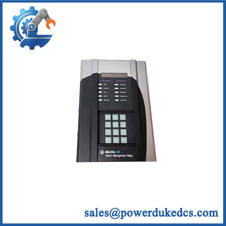
GE 369B1844G5004
Application Scenarios & Pain Points
Micro-case — turbine auxiliary control: A field output stops switching a valve solenoid even though the Nexus controller remains active. When the field wiring and upstream logic have been eliminated, the becomes a practical board-level replacement candidate.
In turbine auxiliary systems, the 16 relay channels can switch discrete field circuits while keeping each channel electrically isolated. The documented 1,000 VAC channel-to-channel isolation is especially relevant when separate field circuits coexist in the same cabinet.
For compressor and balance-of-plant equipment, relay outputs can be used for permissive signals, solenoid control, annunciation, and interposing functions. Check the actual load type; a 7.5 A @ 250 VAC inductive limit is materially different from the 12 A resistive rating.
At high cabinet temperatures, heat generation deserves more attention than the 1.3 W figure suggests. GE documents up to 27 W of heat dissipation when the external control loop associated with relay contacts is included.
With vs. without an exact spare: retaining the correct avoids improvising an output architecture around a transistor card, an incompatible relay board, or a different Nexus I/O generation.
🚨 Common Error Codes & Diagnostic Symptoms
The public documentation does not establish a universal numerical fault-code list for 369B1844G5004. Troubleshooting should therefore begin with channel status, command state, field voltage, relay behavior, and system diagnostics rather than assigning unsupported numerical codes.
Symptom: Commanded output remains electrically open → Diagnosis: The relay contact may have failed mechanically or electrically, or the 24 VDC control path may be absent. Check the control signal and field circuit independently before condemning the relay → Action: Replace the module after confirming the internal relay fault.
Symptom: Output remains energized after command removal → Diagnosis: A welded or mechanically stuck relay contact is possible, particularly after repeated switching of inductive loads beyond the recommended suppression arrangement → Action: Isolate the field circuit and replace the module if contact welding is confirmed.
Symptom: Multiple output channels become abnormal simultaneously → Diagnosis: A common 24 VDC control-power, system-interface, or module-level issue is more likely than simultaneous independent relay failures → Action: Verify module supply, backplane/interface connections, and system status before replacing the .
🚨 Cross-Reference & Lifecycle Migration
Cross-Reference
369B1844G5004 = , identified by GE’s Nexus system documentation as a 16-channel discrete output module with relay output.
Related catalog numbers should not be assumed interchangeable:
- 369B1844G5005 — MDO54: 16-channel digital output module requiring an extension relay board for large-capacity DC control.
- 369B1844G5006 — MDO55: 16-channel transistor output module.
- 369B1844G5007 — MDO56: 16-channel transistor-sink output module.
- 369B1844G5008 — MDO53A: related 16-channel relay-output module.
These are distinct GE item codes with different output technologies or configurations.
Firmware Requirement
The 369B1844G5004 is an I/O module rather than a standalone programmable controller, so there is no documented user firmware-flashing workflow comparable to a Mark VIe controller or PLC CPU.
The Nexus control system itself manages I/O configuration and communications. Replacement work should therefore verify the module’s I/O position, wiring, configuration, and system database rather than assuming that a firmware update is required.
Hazardous-Area Variant Warning
GE documents and as IECEx-certified variants and states that their features otherwise correspond to 369B1844G5004, while their certified relay parameters are different. This is a critical distinction for hazardous-area projects.
Lifecycle Status
Lifecycle: Legacy / Obsolete system generation.
The belongs to the Nexus / OC 6000e turbine-control platform rather than a current general-purpose PLC family. For sites with operating Nexus installations, stock should be managed as critical legacy inventory: preserve exact item identity, maintain tested spares for shutdown-relevant outputs, and document a migration path before the remaining installed inventory becomes difficult to source.
Field Engineer’s Tech Notes
First warning: do not rate the relay from the headline 12 A number. That rating is for specified resistive loads. Inductive loads have lower permissible current, and switching coils or solenoids without suitable suppression can shorten relay contact life. GE specifies 7.5 A @ 250 VAC inductive and 6 A @ 30 VDC inductive.
Second warning: check the exact variant before hazardous-area replacement. The ordinary 369B1844G5004 and IECEx-specific variants are not interchangeable from a certification standpoint. The IECEx variants have specifically defined relay limits, including 8 A/30 VDC resistive and 4 A/30 VDC inductive.
Use ESD protection during handling, and photograph the terminal arrangement before removing the existing module.
Strict QA & Testing SOP
1. Inbound identity verification
Confirm 369B1844G5004 / on the physical label. Record serial number, date code, assembly markings, revision information, and any hazardous-area markings.
2. Mechanical inspection
Check the housing, connector blocks, retaining features, LEDs, terminal interfaces, and PCB areas for cracking, corrosion, contamination, bent hardware, or evidence of previous repair.
3. Relay inspection
Check each accessible relay path for mechanical damage and verify that contact interfaces are clean. Do not rely on visual inspection alone to establish relay condition.
4. Electrical pre-check
Confirm the module’s 24 VDC control interface and perform appropriate resistance/isolation checks using the applicable Nexus maintenance procedure. Do not invent acceptance thresholds where GE documentation does not specify them.
5. Live-rig installation
Install the module into a verified Nexus test assembly with the correct power and I/O interface. Confirm module startup, LED indication, system recognition, and channel response.
6. Channel-by-channel relay test
Command all 16 outputs individually. Verify relay pickup and dropout, contact continuity, response behavior, and absence of unintended cross-channel activation.
7. Load simulation
Use representative resistive and, where appropriate, controlled inductive test loads within the published limits. Confirm that each output returns to the commanded state after repeated operations.
8. Isolation verification
Where test equipment permits, verify the specified isolation between channels and between channel groups and the system according to the applicable maintenance procedure. The published values are ≥1,000 VAC channel-to-channel, ≥2,500 VAC channel-to-ground, and ≥3,000 VAC channel-to-system.
9. Final preservation
Place the approved module in ESD shielding packaging, add impact protection, and retain all inspection photographs and measured results with the asset record.
Test videos are available when live-rig verification is performed and the buyer requires visual evidence of functional testing.
Buyer’s FAQ
Is 369B1844G5004 a 16-channel relay output module?
Yes. GE’s Nexus documentation identifies 369B1844G5004 as , a 16-channel discrete output module with relay output.
Can I use an -CBAUS instead of 369B1844G5004?
Do not make that substitution based only on the name. GE’s IECEx documentation states that has the same general features as 369B1844G5004 but uses specifically certified relay parameters. Certification and load limits must match the installation.
Can the module be hot-swapped?
Do not assume that an energized replacement is acceptable merely because the module is removable. The appropriate procedure depends on the Nexus cabinet architecture, system operating state, field voltage, and site electrical-safety rules. For turbine control equipment, de-energized replacement under an approved maintenance procedure is the conservative default.
How do I verify New Original condition and warranty?
Request photographs of the actual 369B1844G5004 unit, including the GE identification label, board/assembly markings, connectors, and packaging. A legitimate warranty record should state the condition classification, test scope, warranty duration, and serial/date identification of the shipped unit.
For an obsolete Nexus spare, retain GE item code + designation + exact hardware revision + serial/date code + certification status + COO + QC record + packaging condition as one controlled asset record.











 Start Chat


