

Description
- Brand: GE Multilin
- Full Model Number: 469-P1-HI-A20-E
- System/Series Family: Multilin 469 Motor Management Relay
- Core Function: Protection, control, and monitoring of medium- and high-voltage motors
- Top 3 Hardcore Specs: 1 A / 5 A CT inputs | 50/60 Hz | RS485 Modbus communications
- Control Power: 90–300 VDC / 70–265 VAC
- Display: 40-character illuminated LCD
- Protection: Thermal overload, phase differential, ground fault, current/voltage protection
- Stock Status: New surplus, factory sealed, or fully tested refurbished subject to exact inventory confirmation
The GE Multilin 469-P1-HI-A20-E belongs to the 469 Motor Management Relay family, designed for protection and management of medium- and high-voltage motors. The 469 combines protection, monitoring, metering, and control functions in a single relay architecture.
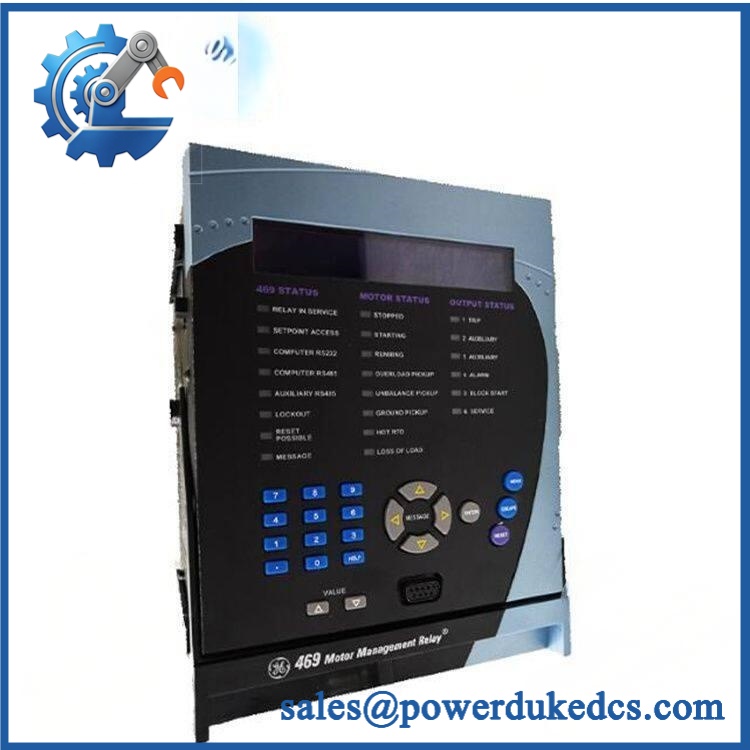
GE 469-P1-HI-A20-E
Module 3: Technical Product Introduction
A motor-management relay sits directly in the protection chain, so replacing it with a superficially similar unit can introduce configuration errors that are not obvious during startup. The GE Multilin 469-P1-HI-A20-E is designed to monitor motor electrical and thermal conditions while providing protective trip and alarm functions. The 469 platform covers medium- and high-voltage motor applications and combines motor protection, metering, diagnostics, and control within one relay.
The relay supports 1 A and 5 A CT inputs, 50/60 Hz operation, and an extensive protection set including thermal overload, phase differential, ground fault, current imbalance, undercurrent, overcurrent, undervoltage, and locked-rotor/stall functions. Communications are provided through an RS485 interface supporting Modbus RTU, while the front panel uses a 40-character illuminated LCD for local configuration and diagnostics. —The exact suffix still matters: option codes determine the installed hardware and should be matched against the original nameplate.
Module 4: Application Scenarios & Field Realities
- For medium-voltage motors driving pumps, compressors, and fans, the 469 can coordinate thermal and electrical protection with motor operating conditions. Motor FLA, service factor, starting current, and acceleration time should be established before configuring trip thresholds.
- On large process motors, phase differential and ground-fault protection can provide additional fault coverage beyond basic overload protection. CT polarity and phase identification must be checked carefully; a wiring error can invalidate the intended protection scheme.
- In applications requiring remote motor data, the RS485 interface and Modbus RTU communication can provide access to measurements, alarms, and relay status. Confirm the existing slave address, baud rate, parity, and termination before reconnecting the communications cable.
- During an outage replacement, preserve the original relay’s complete settings file before removal whenever possible. Protection thresholds, CT ratios, voltage inputs, RTD configuration, trip logic, auxiliary outputs, and communication parameters should not be reconstructed from memory.
Module 5: Migration, Compatibility & Installation Traps
Replacement Matrix
| Replacement Type | Assessment | Engineering Requirement |
|---|---|---|
| Drop-in Replacement | Potentially yes for an identical 469-P1-HI-A20-E configuration | Match complete order code, CT configuration, control power, options, terminals, and firmware |
| Software Compatible | Configuration-dependent | Restore motor settings, protection curves, RTD inputs, outputs, communications, and logic |
| Hardware Modification Required | Potentially required for a different 469 configuration | Verify panel cutout, terminal layout, option hardware, and wiring |
Field Traps — Watch Out
1. Decode the complete order code: The P1-HI-A20-E suffix should not be ignored. GE uses option codes to define relay hardware and functional configuration. Compare the complete nameplate against the replacement before installation.
2. CT secondary rating: The 469 supports 1 A or 5 A CT inputs depending on configuration. Verify the installed CT secondary rating before connecting the relay. Never open-circuit an energized CT secondary.
3. Protection settings are motor-specific: Thermal model parameters, motor FLA, service factor, acceleration time, RTD settings, current imbalance limits, ground-fault levels, and trip delays must be checked against the motor data and existing protection study.
4. Phase differential wiring: If the installation uses phase differential protection, verify CT polarity, phase correspondence, and wiring before enabling the function. A relay can pass its internal self-test while the external differential circuit remains incorrectly wired.
5. Communication configuration: For Modbus RTU integration, record the existing slave address, baud rate, parity, and physical RS485 wiring. Do not assume the replacement will retain the previous communications configuration after initialization.
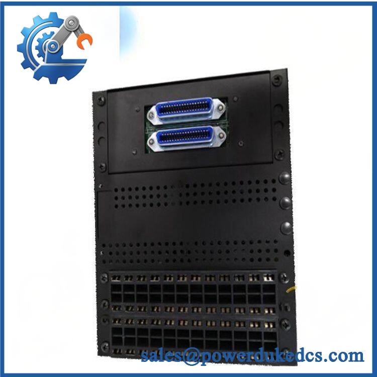
GE 469-P1-HI-A20-E
Module 6: Quality Assurance SOP
Before shipment, each GE Multilin 469-P1-HI-A20-E should undergo a documented relay-testing sequence appropriate to the exact hardware configuration.
- Step 1 — Part-number verification: Record the complete 469-P1-HI- order code, serial number, hardware revision, firmware revision, and all visible GE Multilin identification.
- Step 2 — OEM anti-counterfeit visual inspection: Inspect GE Multilin labels, LCD, keypad, status LEDs, terminal blocks, communication ports, PCB markings, and manufacturing identifiers. Photograph the complete nameplate.
- Step 3 — Physical condition inspection: Check the enclosure, display, keypad, terminal blocks, connectors, mounting hardware, and PCB for corrosion, contamination, cracked components, damaged terminals, loose hardware, or evidence of previous repair.
- Step 4 — Control-power verification: Confirm the exact auxiliary-power requirement before energization. The applicable 469 configuration should be checked against its nameplate and documentation rather than assuming a generic 469 supply rating.
- Step 5 — Power-on self-test (POST): Energize the relay under controlled conditions and verify LCD initialization, keypad response, status LEDs, diagnostic messages, and startup behavior.
- Step 6 — Current-input verification: Apply calibrated current signals to the CT inputs and verify phase-current measurement, scaling, and phase identification. Confirm the test configuration matches the relay’s 1 A or 5 A input arrangement.
- Step 7 — Voltage-input verification: Apply appropriate calibrated voltage signals and verify voltage magnitude, phase relationship, frequency, and phase-sequence detection.
- Step 8 — Protection-function verification: Use a relay test set to exercise representative thermal, overcurrent, undercurrent, phase-loss, current-imbalance, ground-fault, undervoltage, and other applicable protection functions.
- Step 9 — RTD and analog-input verification: Where the exact configuration supports these inputs, simulate representative RTD and analog signals and verify measurement and alarm response.
- Step 10 — Output verification: Test trip, alarm, auxiliary, and control outputs relevant to the installed configuration. Record contact operation and terminal assignments.
- Step 11 — Communication handshake verification: Test the RS485 interface using an appropriate Modbus RTU test environment. Verify address, baud rate, parity, response, and representative register reads.
- Step 12 — Final photographic record: Photograph the complete relay, model/order-code label, serial number, display, terminal area, communication ports, and final packaging.
QA release criterion: A successful power-up is only a basic hardware check. A fully tested 469-P1-HI- should have documented current, voltage, protection, output, display, and communication verification appropriate to its exact configuration. Final commissioning should additionally verify CT polarity, phase sequence, motor-specific protection settings, trip logic, interlocks, and coordination with the upstream protection system.











 Start Chat


