

Description
- Brand: GE Multilin
- Full Model Number: 469-P1-HI-A20
- System / Series Family: Multilin 469 Motor Management Relay
- Core Function: Motor protection, control, metering, monitoring, and diagnostic relay for medium- and large-sized motors
- Top 3 Hardcore Specs: 1 A phase CT inputs / 90–300 VDC or 70–265 VAC control power / Four 4–20 mA analog outputs
- Construction: Drawout relay
- Phase Current Input: P1 — 1 A phase CT secondaries
- Control Power: HI — 90–300 VDC or 70–265 VAC at 48–62 Hz
- Analog Outputs: A20 — Four 4–20 mA outputs
- Display: Standard display configuration
- Communications: RS485; additional protocol capability depends on installed option
- Stock Status: New Surplus / Factory Sealed — exact physical condition to be confirmed before quotation
The GE 469 order-code documentation confirms that P1 specifies 1 A phase CT secondaries, HI specifies the high-range control-power supply, and A20 specifies four 4–20 mA analog outputs.
Module 3: Technical Product Introduction
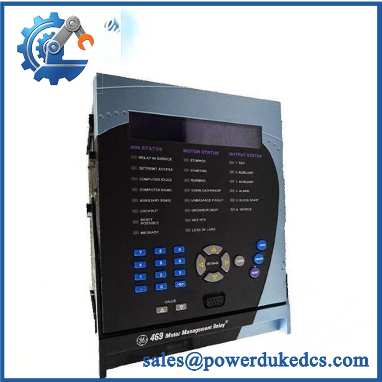
A motor protection relay failure can remove trip protection, monitoring, metering, and control functions from the same feeder at once. The GE Multilin 469-P1-HI-A20 is a drawout 469 Motor Management Relay configured with 1 A phase CT inputs, high-range control power, and four 4–20 mA analog outputs. The 469 platform provides motor protection functions together with RTD monitoring, event recording, metering, programmable inputs/outputs, and communications. The relay uses a configurable architecture rather than functioning as a simple overload device.
The HI power option is important during replacement: the relay accepts 90–300 VDC or 70–265 VAC at 48–62 Hz. GE explicitly warns that the applied control voltage must match the installed power-supply specification. The P1 option uses 1 A phase CT secondaries, while A20 provides four 4–20 mA analog outputs for integration with control or monitoring systems. The relay also provides an RS485 interface, with terminal documentation identifying RS485 positive, negative, and common connections.
Module 4: Application Scenarios & Field Realities
- For medium-voltage motor feeders, the 469 combines electrical protection with motor thermal and operating-condition monitoring. Before replacing one, capture the existing CT ratios, motor FLA, acceleration characteristics, trip settings, and output logic.
- Where the control system depends on analog process feedback, the A20 configuration matters. Four 4–20 mA outputs can be assigned within the relay’s configuration, so the replacement should retain the existing output mapping rather than relying on default settings.
- On large pumps, compressors, fans, and other critical motors, the 469’s RTD inputs can monitor motor temperatures alongside electrical measurements. The terminal documentation provides dedicated connections for multiple RTD channels, so incorrect RTD reconnection can create false temperature alarms or remove expected protection.
- During a relay replacement in an MCC or switchgear lineup, the drawout construction can simplify physical exchange, but it does not make the job electrically automatic. CT circuits, VT connections, control power, trip circuits, and grounding still require controlled isolation and verification.
Module 5: Migration, Compatibility & Installation Traps
Replacement Matrix
| Replacement Case | Classification | Engineering Requirement |
|---|---|---|
| 469-P1-HI-A20 replacing the identical 469-P1-HI-A20 | Drop-in Replacement | Verify order code, control power, CT inputs, analog outputs, settings, and wiring |
| Another 469 with the same P1-HI-A20 configuration | Software Compatible — Verify First | Confirm firmware, hardware revision, configuration, and protection settings |
| 469 with P5 instead of P1 | Hardware Modification Required | Phase CT secondary rating changes from 1 A to 5 A |
| 469 with LO instead of HI | Hardware Modification Required | Control-power range is different |
| 469 with a different analog-output option | Hardware Modification Required | Recheck the connected control-system analog inputs |
| Different Multilin relay family | Hardware Modification Required | Re-engineer CT/VT inputs, protection logic, wiring, communications, and settings |
Field Traps — Watch Out
Control-power mismatch: The HI version accepts 90–300 VDC or 70–265 VAC at 48–62 Hz. GE’s installation documentation specifically warns that applying an incompatible control voltage can damage the relay. Verify the rating on the actual drawout-unit label before energization.
P1 versus P5: The first option position identifies the phase CT secondary rating. P1 = 1 A, while P5 = 5 A. A P5 relay should not be substituted into a P1 installation without engineering review of the CT circuit and protection settings.
A20 output configuration: A20 identifies four 4–20 mA analog outputs. Confirm which relay quantities are assigned to those outputs before disconnecting the existing unit. Otherwise, the replacement may power up normally while the plant DCS receives the wrong measurements.
RS485 wiring: The terminal list identifies RS485 +, RS485 –, and RS485 common at D25, D26, and D27. Preserve polarity and common wiring during replacement.
CT circuit safety: Never open-circuit an energized current-transformer secondary. CT isolation and shorting procedures must follow the site’s approved electrical safety procedure before the drawout relay is removed.
GE 469-P1-HI-A20
Module 6: Quality Assurance SOP
The pre-shipment inspection for a GE Multilin 469-P1-HI-A20 should verify the complete order-code configuration and the relay’s principal protection interfaces:
- Part-number verification — Confirm the complete identification as 469-P1-HI-A20 and record serial number, hardware revision, firmware revision, and visible manufacturing information.
- OEM anti-counterfeit visual inspection — Examine the GE Multilin nameplate, faceplate, LCD, enclosure, terminal markings, connectors, PCB markings, and manufacturing identifiers for inconsistent printing or unauthorized modification.
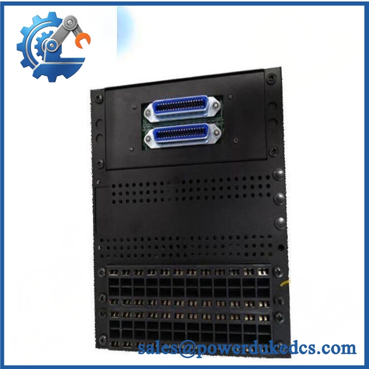
- Mechanical inspection — Check the drawout housing, extraction mechanism, terminal blocks, rear connectors, faceplate, display, mounting hardware, and accessible PCB areas for cracks, corrosion, deformation, contamination, or impact damage.
- Configuration verification — Confirm P1, HI, and A20 against the physical identification and test documentation. These three ordering-code positions directly affect CT input rating, control power, and analog outputs.
- Power-on self-test (POST) — Energize the relay using a controlled supply within the verified HI range and check startup behavior, LCD operation, self-test status, alarms, and diagnostic indications.
- Current-input verification — Using an approved relay test set, inject controlled phase-current signals appropriate to the 1 A CT configuration and verify measurement accuracy and applicable protection responses.
- RTD verification — Test representative RTD channels with an approved simulator and confirm temperature measurement, alarm, and diagnostic behavior.
- Analog-output verification — Test all four A20 4–20 mA outputs across their applicable operating range. Confirm that each output responds to the configured relay quantity and does not remain fixed at an unexpected value.
- Communication handshake verification — Test the RS485 interface using the applicable 469 communications configuration. Verify transmit/receive behavior, addressing, and communication integrity without assuming that every 469 has identical protocol options.
- Protection-function verification — Perform controlled secondary-injection testing for the applicable motor-protection functions specified by the test procedure. Record pickup, timing, trip, alarm, and reset behavior.
- Relay-output verification — Verify applicable trip, auxiliary, alarm, block-start, and service relay contacts using a controlled test sequence. The 469 terminal documentation identifies these relay contacts individually.
- Final inspection and packaging — Photograph the exact 469-P1-HI-A20 label, record firmware and test results, protect the drawout contacts and faceplate, apply appropriate ESD precautions, and package the relay against mechanical shock and moisture.
The final QA record should connect the 469-P1-HI-A20 order code, P1 1 A CT configuration, HI power verification, A20 analog-output test, protection test results, RS485 test, firmware information, and final packing record to the exact unit shipped. For this relay, the complete order code is a critical engineering identifier rather than a simple catalog suffix.











 Start Chat


